This thread has been locked.

If you have a related question, please click the "Ask a related question" button in the top right corner. The newly created question will be automatically linked to this question.

LP5912DRV33EVM: Current consumption of LP5912

Part Number: LP5912DRV33EVM
Other Parts Discussed in Thread: LP5912

Hi,

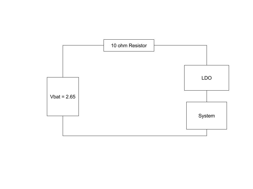
We made a custom board with nordic nrf52 for an BLE application. In that We used LP5912 3.3 V LDO. We profiled the custom board for the current consumption. The LDO seems to consume ~100 uA. Is this expected? or are we doing something wrong? Vin is 2.84V. Vout (measured) 2.65V.

Thanks and regards,

Sathish V

  • Hello Sathish,

    You are correct, 100uA is higher than expected. Per the datasheet chart "Figure 13. LP5912-3.3 IQ (No Load) vs VIN" I would expect to see less than 40uA with no (zero) load current. This would also be exclusive of any current into the PG pin, which would be low under these conditions .

    A schematic, indicating how (where) you are measuring the LP5912 current, might be helpful.

  • Hi Jones,

    Sorry for the late reply. The rough block diagram of the schematics is attached. In that, every time, we measure the voltage across the resistor 10 ohm. From that we derive the current consumption. To figure out how much current LDO is using, we measured the current when LDO is bypassed. From the difference, we came to know that it is consuming 90 to 100 uA. Is this correct way to measure?

    Current measure with LDO = 0.720 mA

    Current measurement with LDO bypassed = 0.630mA

    This is the data of one of the trial.

  • " ... Is this correct way to measure? ..."

    If I understand your description correctly ... Maybe, but certainly not ideal.

    In this case you would be measuring: (LP5912-3.3 Ignd with load + 'System Load Current') - (LP5912 Ignd with no load + System Load Current)

    If you look at "Figure 19. LP5912-3.3 IGND vs IOUT" in the LP5912 datasheet you will see that it does not take too much load current to cause the LP5912 IGND current to go above 100uA. Note that Figure 19 is for the 'Recommended Operating Condition' where Vin= Vout+0.5V= 3.8V, while you are testing with LP5912 operating in dropout mode (Vin~2.65V).

    So, with LP5912-3.3 providing a 'System Load Current' of 630uA, and 'Viin<(3.3V+Vdo' (i.e. in dropout mode) it is very possible that 100uA is correct.

  • Thank you for the response jones. So if im right, if I give 3.8 V to Vin, then I should see current consumption less than 100 uA correct?  I will give it a try.

    If I provide Vin more than 3.8V , what will be the current consumption of  the LDO? Im not able to get this data in the datasheet.

  • With Vin of 3.8V you will be out of dropout mode and in the recommended operating Vin range. Current used by the L5912 should drop measurably from what you are seeing with present Vin. Actual current consumed by the LP5912 will depend on the load current. 

  • Hi,

    Sorry for replying late. Got stuck with some other work.

    result 1:

    I tried providing 4.7 V at Vin of LDO. The setup remained same as mentioned above. I measured current consumption of overall system as 830 uA. Note: Before LDO we have a resister network of (120 k) for battery measurement. This was consuming 37 uA. 

    result 2

    After this we bypassed the LDO and the resister network, and provided Vin as ~3.27V. In this case we observed current consumption of 740 uA. 


    So, Now to get the current consumed by the LDO, we have to subtract, result 1 and result 2.

    so Ildo = 830 - 740 = 90 uA. But this contains the resister network's current consumption. So we removed 37 uA from the result, so the real Ildo = 50 uA.


    Is this result correct? . According to the figure 13. Iq vs Vin, I should be expecting 25 - 30 uA. But according to the figure 19. Iq vs Iout, the result should be around 60 to 70 uA. Which should I consider? were my observation correct.

    Thanks & regards,

    Sathish V

  • Figure 13 does not apply here since your load current is not zero.

    If I recall correctly the data line for Figure 19 is for load current from 1mA to 500mA.

    Based on your description, in your circuit, the calculated 50uA value should be correct.

  • Thank you jones for your patience for answering my questions. I think I got the answer for what Im looking for.