Other Parts Discussed in Thread: LM5121, TPIC74101
Hi
I am using TP55332 IC for one of my application. The DC-DC converter is designed to operate as BOOST converter which provides 18.5V regulated output voltage from the input voltage range of 8V to 18V.
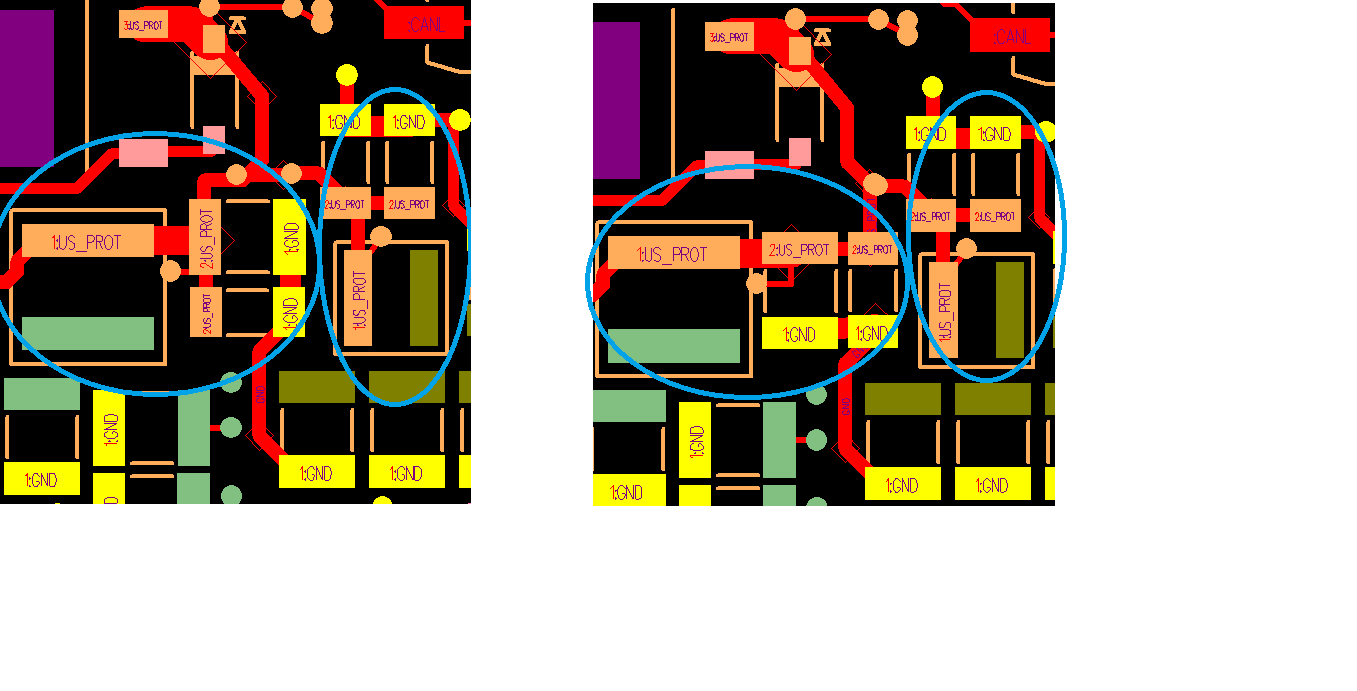
I want to know to compensation circuit values, so that with proper layout and correct compensation values, stability will not get affected.
Details of my circuit:
The operating frequency of my DC-DC converter is 350kHz,
output voltage is 18.5V, and output current is 1A
Chosen Inductor is 22uH power inductor
and output capacitance of 4.7uF x 3 ceramic capacitors,
Input Capacitor is 4.7uF x 2 ceramic capacitors.
So, what should be the compensation values of Resistor and capacitor, so that the circuit will be stable?
I tried calculating from the datasheet, but unable to do it. Can you tell us how to calculate the values?
Also, I see the switching power losses in this switching regulator is very high, can any adjustments made so as to reduce the switching losses?
And for the EMI filter calculations of boost converter, can we use the Application note "AN-2162 Simple Success With Conducted EMI From DC-DC Converters" of Texas Instruments? Kindly suggest.
Thanks and Regards
Pratima V.