I have been doing brown out testing on my product recently as we have been finding that it is entering an unknown state and not recovering if the input voltage dips too low. I am half wave rectifying 24VAC and feeding the result into the LM22680 to create a 3.3V rail. Upon investigation, it looked like the regulator was not regulating correctly when the input ripple dropped low enough so I added a voltage divider to the enable pin to utilize the UVLO feature of the chip. Before the addition it would start behaving erratically at 6.8VAC, after the addition it had the same problem at the new 15VAC limit I setup. I connected it to a DC power supply and the UVLO works perfectly and cuts out exactly when I would expect it to, but when connected to the ripple of the rectifier it seems to affect it and it droops but doesn't turn off as I would expect. I expect the UVLO to shut off the output when the input voltage drops below the threshold in the spec sheet (~1.6V at the enable pin) and then not turn on again until it rises back up through the hysteresis voltage (+0.6V), but this is not what I'm seeing.
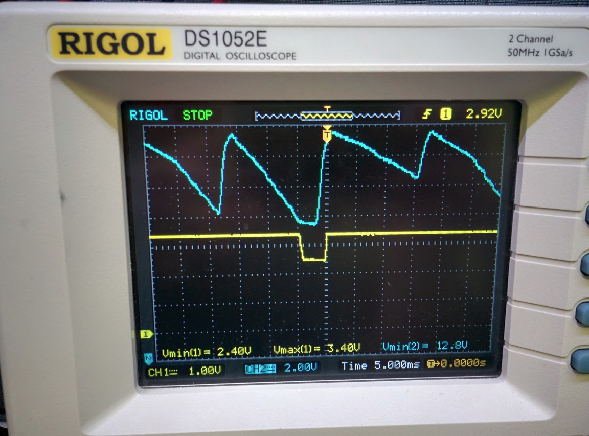
The picture below shows the resulting waveforms with the UVLO circuit connected. The blue trace is the input ripple (2V/div, zero is off the screen), yellow trace is the output from the regulator (1V/div, zero is -3V from center marked by the yellow 1 on the left side). The ripple drops low enough to trip the UVLO, which cause the output voltage to drop from 3.40V to 2.4V for 4.2mS until the rectifier cap is able to start charging again and bring the input voltage to an acceptable level again.


