This thread has been locked.

If you have a related question, please click the "Ask a related question" button in the top right corner. The newly created question will be automatically linked to this question.

TLV431: PWM "constant current" sink application

Part Number: TLV431

Hi all,

I am trying to build a constant current sink using the TLV431 as a voltage reference and a NPN BJT (BC549C) on the output.

The circuit is shown below:

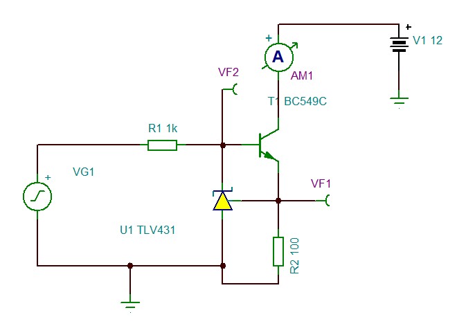
VG1 is the PWM signal (0-5V nominally), AM1 is used to monitor the current flowing from the 12V battery while VF1 were used to monitor the voltage across the base and the emitter of the bjt.

From the simulation it seems to work, and from bench testing it seems to work too.

However I am not sure if I forgot anything, especially regarding the OFF state phase, where the Vref pin voltage is not regulated. What do you think?

Thank you for your help and time,

Andrea C.

  • Hi Andrea,

    The circuit looks correct. The only thing to watch out for is stability.

    If you start seeing some oscillations at high frequencies I'd recommend adding a small capacitor between VF1 and VF2.

    Regards, Diego
  • Hi Diego,

    thank you for your reply. On the scope I don't see any weird oscillation, maybe a little bit of overshoot in the step response.

    I will experiment a little bit with the caps as you suggested.

    Thank you again,

    Andrea C.