This thread has been locked.

If you have a related question, please click the "Ask a related question" button in the top right corner. The newly created question will be automatically linked to this question.

TPS65185EVM: Not giving output voltage

Part Number: TPS65185EVM
Other Parts Discussed in Thread: TPS65185, TPS65186

Dear Manager,

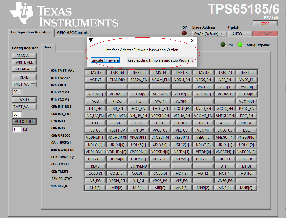
My TPS65185EVM is not giving output voltages (22v, -20v, -15v, 15v) from last 2 days, all output voltages are Zero Volts.

Please guide me how to can I troubleshot and how to fix the issue.

Regards,

Tanveer

  • Hi Tanveer,

    Was the EVM working previously? If not, are you supplying 3.3V to the VIO rail on the EVM?

    If the EVM was working before, does it make an attempt to start up at all?

    Faults like shorted outputs can cause the PMIC to shut down, and the interrupt registers INT1 and INT2 can identify which regulators are suspect. A quick way to reset the pmic is to clear the interrupts by toggling the wakeup pin and then initiate a new startup sequence by toggling the pwrup pin.

    Best Regards,
    Rick S.
  • Dear, Richard Solarski,

    Thanks for your reply.

    Yes, EVM was working before.

    Based on your guidance I have tried by toggling WAKEUP and PWRUP pins but its still same, output voltage is Zero.

    Please guide me the steps to reset PMIC.

    and plz guide me to troubleshoot if some component is faulty.

    Regards,

    Tanveer
  • Hi Tanveer,

    Power-cycling is enough to reset the PMIC.

    With WAKEUP high, what are the values of INT1 and INT2? These registers will indicate which regulator is at fault.

    Best Regards,

    Rick S.

  • Dear Richard Solarski,

    plz see my software screen below for your reference to see INT1 and INT2, if these are some.

    Also please note that there is a popup Interface adapter firmware have wrong version. and asking me to update.

    More over when i power ON device it takes .5 Amp. When I put WAKEUP jumper to VIN it is taking .8 amp, it looks it is going to wakeup mode.

    But all other output voltage is Zero.

    Hope these infos are helpful for you to guide me further.

    Looking forward for your valuable comments

  • Hi Tanveer,

    If .8 Amp is not a typo then the device sounds like it is damaged. You shouldn't be seeing 500mA or 800mA on the EVM, as the PMIC will operate with just a few milliamps with no loads attached. If this is the case, system level ESD may have damaged the device.

    For the GUI, you should be able to updated the firmware of the USB-to-GPIO and continue using it. You will have to change the slave address to 0x68h in the top right corner to communicate with the part.

    Some user's have had issues with the adapter, but in that case any i2c adapter should be able to poll the PMIC at the slave address of 0x68h, where the interrupt register address is 0x08h. However, given the quiescent current consumption on the EVM it may not be able to communicate at all.

    Best Regards,

    Rick S.

  • Dear Richard Solarski,

    Thanks, for your continuous replies and valuable support.

    My Variable Power Supply is showing 0.05 Amp at power on and 0.08 Amp at wakeup, is it OK?

    What are the main causes which can damage the device, actually we have to use TPS65185/6 in production in bulk.

    I have TPS65186 IC with me, If you can guide me to make sure if the device is damage, may it be repaired by just changing the IC or there is some thing else to check in the case of damage.

    Regards,

    Tanveer
  • Hi Tanveer,

    Typical current consumption in the datasheet, with all regulators switching and no loads attached, is 5.5mA, so 80mA with no switching indicates potential damage to the silicon.

    Electrical overstress can be caused by various conditions, possibly from exceeding the absolute maximum ratings in table 7.1 of the datasheet, or accidental current surges due to events such as hot plugging or static discharges, which is not unrealistic given the nature of an exposed EVM. For example, a short from the VB test point to the VIN terminal would lead to 20V on a pin designed to withstand only 7V max.

    If the silicon is damaged the part would have to be replaced.

    Best Regards,

    Rick S.

  • Dear Richard Solarski,

    Great Guidance, Thanks.

    by silicon damage you mean TPS65185 chip is damaged.

    If it is so, i have an extra TPS65186 (TI 2CI, AXNC G4) chip with me, if i just replace it, the EVM will be OK?

    OR

    Is there any other silicon on the EVM which may be damaged?
  • Hi Tanveer,

    The TPS65186 has a different pin-out than the TPS65185 and would not function properly on the TPS65185 EVM.

    Best Regards,

    Rick S.

  • Dear Richard Solarski,

    Thanks for your guidance.

    I bought TPS65185EVM from China, now a days I am in Pakistan,

    1.How can I get TPS65185EVM (2 pcs) boards only (no need USB cables and USB Adapter) and TPS65185 IC(2pcs) to finish my R&D.

    2. My final product will be eReader with eInk display of 6", 9" etc. which one is the best for this; TPS65185 or TPS65186

    3. Please give meTPS65185 or TPS65186 SCH, and PCB Layout to embed it to my main board.

    Regards,

    Tanveer

  • Hi Tanveer,

    The TPS65185 might be beneficial as it has similar functionality but allows for active discharge on the power rails.

    Since the EVMs are orderable on the TI.store, you may have to submit a help request through the store for shipping availability.

    EVMs are only for device evaluation, not for direct use in end products. Any layout and schematics provided are purely for reference. However, E-ink provides full evaluation kits for implementing their screens and provide hardware and software support directly for end products.

    Best Regards,

    Rick S.

  • Dear Richard Solarski,

    Thanks fro your valuable support.

    Can you please refer me some power supply kit for 6" and 9" eInk display.

    I would plan to make a module based on TPS65185 and interface it with my main board, what do you suggest me about it.

    Is such module can bear load of 6", 9" eInk display?

    For this reason i need SCH and layout of your EVM so that i can make changes in it and get a final module.

    Looking forward for your expert opinion.

    Regards,

    Tanveer