This thread has been locked.

If you have a related question, please click the "Ask a related question" button in the top right corner. The newly created question will be automatically linked to this question.

EMB1428Q: In-rush current limiting circuit question

Part Number: EMB1428Q

Hi team,

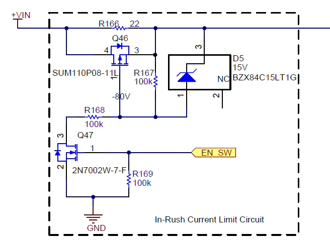
My customer is designing 12-cell active balance product refered to our TIdesign TIDA-00817 and TIDA-00239. And now they have one question about the in-rush current limiting circuit.

In our reference guide document "SLUUAS6A", it says the below circuit is used to limit the in-rush current for the FET switch-matrix. I don't why it's the in-rush current into FET switch-matrix. According to the schematic(below link), the circuit doesn't connect directly to the FET switch-matrix. 

www.ti.com/.../tidr709.pdf

Could you help explain it for me?

Thanks,

Will

  • Hi Will,

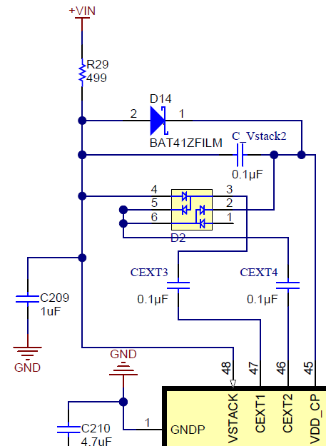
    It is limiting the inrush current to the +VIN node of of the schematic. This node is tied to the VSTACK pins of the EMB1428's. This is one of the main power supplies and also the input to the EMB1428 charge pump used to give generate the supply for the floating gate driver. I am pretty sure it is to protect the charge pump
  • Hi David,

    Thanks for your reply. 

    I checked the schmatic, and find there are two resistors R23/R29 499Ω between Vin and VSTACK. What are these two resistors function? Does these two resistors used to limit the in-rush current? If so, why we use another in-rush current limiting circuit to limit the in-rush current?

    Regards,

    Will

  • Hi Will,

    Truthfully, i am not sure. I can dig deeper into the EM1401 schematic. Please note that the original designer of the EVM is no longer with TI, so it may take a little longer for me to find out. It may be that the inrush is there to some other function and that i am mistaken.

    For what it's worth, the EM1402 does not utilize the inrush protection on the stack, and has successfully been implemented.
  • Hi David,

    I have checked the schematic and find the Vin also connect to the primary side of the bidirectional DC/DC converter, and there is 3 2.2uF in parallel, so if this circuit is used to limit the inrush current into the caps.
    And if so, I wonder if it is necessary to add this circuit to limit the current into the caps, or can we tell the customer they can omitted this inrush circuit?

    Thanks and Best Regards,

    Will
  • Hi Will,

    Seems i was mistake, there is an inrush current limiter in the em1402 as well. It is used to protect the FET gate drivers for the DC-DC. I would be willing to bet it is used in a similar fashion on the em1401.

    Our load switches team actually put together a good app note discussing the problems caused by inrush current into capacitors: www.ti.com/.../slva670a.pdf

    I would recommend keeping it. To me, it seems like a measure to add robustness to a design. I'm sure it will work without the design, but they may have occasional damaged boards/ ic's