This thread has been locked.

If you have a related question, please click the "Ask a related question" button in the top right corner. The newly created question will be automatically linked to this question.

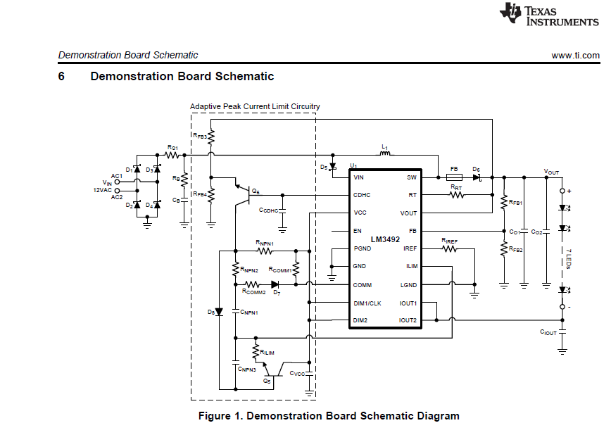
LM3492AR111DEMO: peak current limit circuitry

Part Number: LM3492AR111DEMO

Hi,

Can anyone explain the current limit circuitry? Why the LED current is set at 360mA but from what i measured the LED current is limit at around 200mA.

What is the purpose of the peak current limit circuitry?

Regards,

FY

  • Hello FY,

    I am not sure about the low current reading. But I believe that circuit adjusts the current limit and the output voltage to keep the input current constant. Without it the input current would be high at the beginning/end of the cycle and low in the middle resulting in a low power factor.

    However I am not 100% positive. Our AC-DC expert is out for a few days but I will forward this to him for when he gets back. He will know more about this than I do.

    Regards,

    Clint

  • Hello FY,

    Iref sets the current regulation for the two output channels.  To get over 200 mA the two outputs have to be paralleled.  If you are measuring 200 mA perhaps one of the channels isn't providing current or the input source is different than the DEMO board.  If Iref is around 6.25 Kohm it will be set for 200 mA per channel.  If the channels are paralleled around 400 mA.  It will also depend on what the input voltage source is.

    Ilim sets the peak current trip threshold, if the pin is open this is around 3.9A.  This is for protection such as preventing saturation of the inductor or excess MOSFET current for high duty-cycles.

    Thanks,

  • Hi Irwin,

    Thank you for the explanation. Is there any reference on adjusting the Ilim in this configuration?

    Regards,

    FY
  • Hello FY,

    It really has to do with your design, the inductor, switching frequency, duty cycle and output current.  If you leave it disconnected it defaults to 3.9A.  If your inductor can handle that you can use it that way.  If you want to set it lower I can help if you need it.

    An example would be input 12V, output 24V, this makes the duty cycle 50%.  If there was no ripple the input current would be 2X the output current because it's only on 50%of the time, the output current through the rectifier would be the same, 2X at 50% duty cycle.  There will also be inductor ripple current that makes this number higher.  It can be a small percentage or a large percentage depending on inductor value, switching frequency, input voltage and duty cycle or output voltage.

    Another example would be the same output, 24V and 6V input.  They duty cycle would be 75% on the input, 25% on the output rectifier.  This means the current needs to be 4X the output current, Iout/25%.  Again there is ripple.

    Worst case if you hit Ilim you will see the led current start dropping when you lower the input voltage.

    If you want me to calculate this let me know.

    Regards,