This thread has been locked.

If you have a related question, please click the "Ask a related question" button in the top right corner. The newly created question will be automatically linked to this question.

LM10506: Switching between PFM and PWM mode when in forced PWM mode

Part Number: LM10506
Other Parts Discussed in Thread: , LM26480

Hi,

We are currently using the LM10506 in this configuration:

LDO 3V2 @10mA

Buck1: programmable from 2V5 to 3V0 20mA to 80mA

Buck2: programmalble from 2V5 to 3V0 20mA to 80mA

Buck3: fixed 1V2 10mA

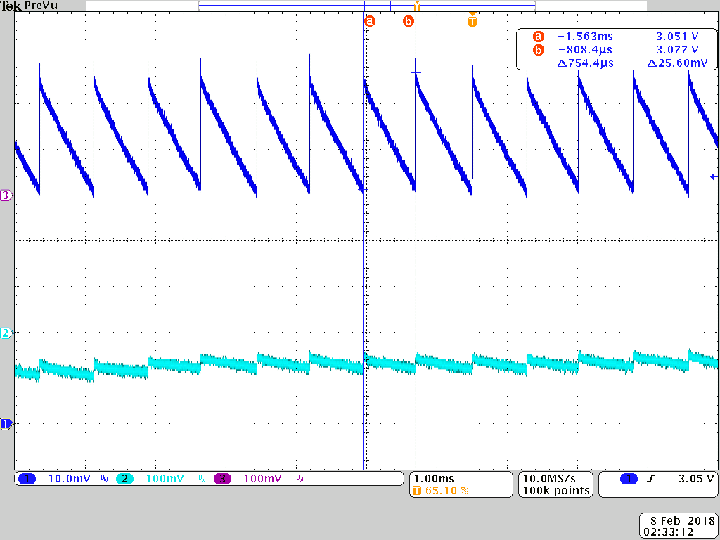
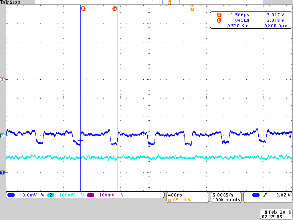
We have (for EMC-reasons) chosen to have the switchers run in forced PWM mode.

It seems that when the load changes from 80 to 20mA on the buck 1 and 2 then they change from PWM to PFM regardless of the "forced PWM" setting.

Is there anything we can do to avoid this? any settings? or do we have to add a minimum-load?

The buck3 is always in pfm mode regardless. It would be great to have the possibility to have this in PWM mode also.

I know that we are sacrificing efficiency, but that is the trade-off, we are willing to make.

Best regards,

Bent

  • Hi,

    I have assigned your request to responsible Applications Engineer and we will get back to you as soon as possible.

    Regards,

    Murthy
  • Bent,

    Do you have a schematic you can share and scope shots showing the transition from 80 to 20mA load while probing the switching node?

    I am not sure what you mean when you say "buck3 is always in PFM."

    Reg. 0x0A, Buck Control, has 3 bits for Force PWM settings where Bit 4 = Buck1, Bit 3 = Buck2, and Bit 2 = Buck3
    When bit 2 of Reg. 0x0A is set to '1', Buck3 should be in Forced PWM mode.
  • Hi Brian,

    I will today make the scope shots you ask for, but I can elaborate a little.

    We have all Buck's configured for forced PWM. When the load is 80 mA then everything is in perfect order.

    When we then lower the load, the bucks enter PFM. My question is now, at what load will we see this transision?

    It seems that no matter what we do, we'll see the buck1-->3 enter PFM, regardless of "forced-PWM-setting". Is that right?

    BR
    Bent

  • Bent,

    I tested this on the LM10506EVAL EVM board for all 3 Bucks and clearly saw that Force PWM was effective, even at No Load.

    Attached are two images, both captured while probing LM10506 at Buck1 across the output capacitor (with output Voltage set to 3.0V)

    PFM/PWM Auto Mode (Force PWM = 0)

    PWM-Only Mode (Force PWM = 1)


    This force PWM mode capture clearly shows a period T = 520ns, or fSW = 1/T = 1.92MHz (approx. 2MHz)

    Bucks 2 & 3 exhibited similar behavior with varying pulse size/width in PFM mode.

  • Hi Brian,

    Thank you for your effort, and I have a little update :-)

    We have had to debug the software for setting up the PMU, using an oscilloscope, and there we found that there were rather critical issues in the way our SW-guys were accessing the PMU.

    This caused the PMU to be in PFM where we believed it to be in forced PWM. thus exhibiting this strange behaviour.

    Now we have what we belive is a stable and well-configured system, and I can also see that the switching is at 2MHz.

    This is all the way down to no-load.

    Perfect :-) Thank you for your help so far.

    I have an additional question though: Which mode do you recommend to use, to perform best with regards to EMC?

    I have a half H-bridge switching at 2.8MHz at Buck1 and an additional one on Buck2. In some (many/most)  cases we see the 2.8MHz clearly on the conducted emission measurements.

    Occationally we se absolutely NOTHING.

    Any obvious ideas of what to look for. I know it is difficult to give any destinct answers, but any clue as to where to look for the solution would be highly appreciated.

    I am not sure that I am allowed to share the schematics here, so it cannot be more than guessing. I know that.

  • Bent,

    Regarding the portion of EMC related to the LM26480: The forced PWM at 2MHz will be better for a simple reason. It is more predictable than PFM. PFM will always be lower than 2MHz, and it is likely to create emissions in the AM band of 535-1605 kHz. A single pulse of PFM that repeats whenever the output voltage drops below the lower limit will look like it has a specific frequency at every discrete loading condition. 

    However, I do not think I can help you very much with the emissions of the half H-bridge motor driver, with or without a schematic or frequency plots. EMC/EMI is not my area of expertise, especially when it doesn't involve the PMIC.

  • Brian,

    Thank you for your time anyway.
    quick and thorough answer :-)

    I will see if I can pin this problem down in another way.

    /Bent