This thread has been locked.

If you have a related question, please click the "Ask a related question" button in the top right corner. The newly created question will be automatically linked to this question.

802.3bt - Current Inbalance between pairs.

Other Parts Discussed in Thread: TPS23880, TPS2388, TPS2372-3EVM-757

Hi,

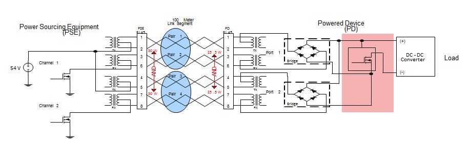
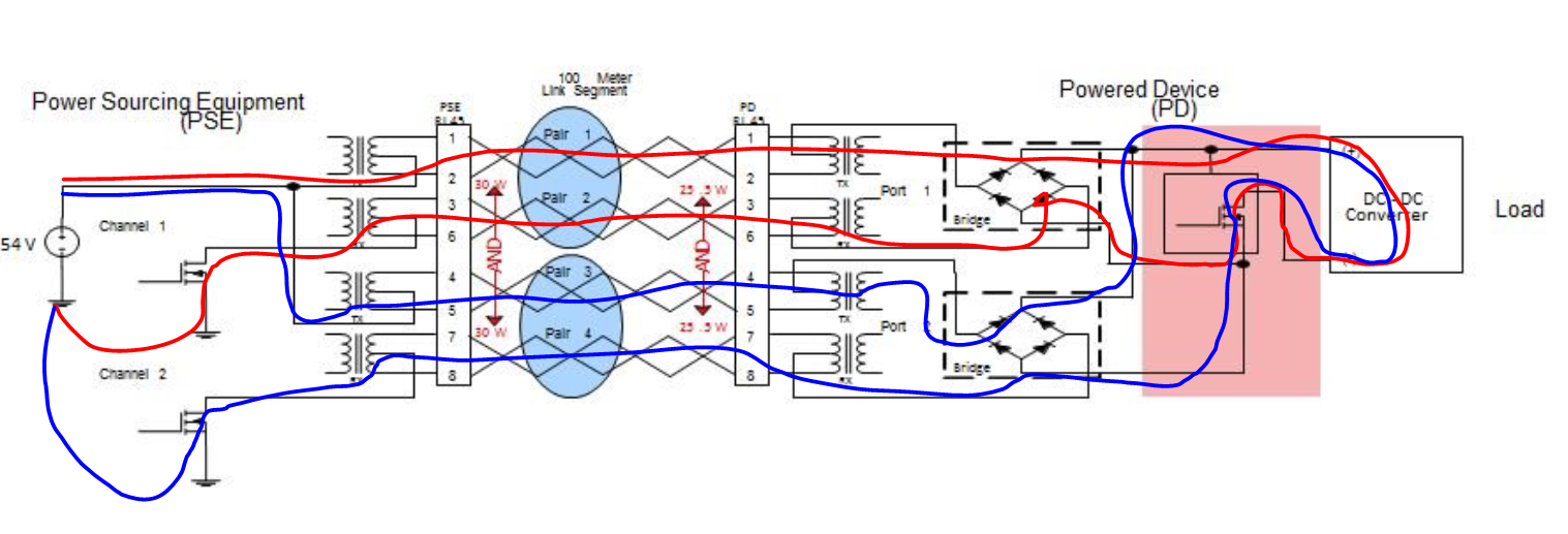
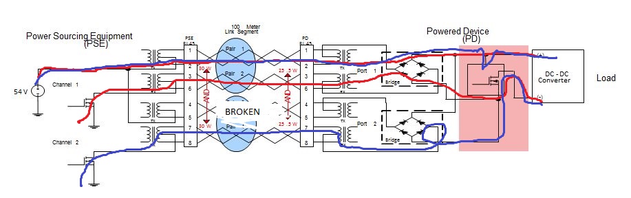
If we are designing a 802.3bt system,  where we  are pushing 90W ( from the PSE ), this implies about 900mA per pair.      If one of the pairs breaks, the current will flow across just one pair, and bad thigns start to happen if yout put 1.8A on a single pair of 23AWG wire.

Is there any mechanism in 802.3bt to shutdown if this happens?     

  • Hi Andrew,

    The PSE device has current limit for each channel/pair set. If the current exceed this limit, the PSE will shutdown the channel. Our PSE has both 4 pair policing and 2 pair policing, so you don't need worry about the situation you described above. The PSE device will take care of the over current itself. Thanks.

    Best regards,

    Penny

  • this suggests that each pair needs to have more than one current sense? Is there two Fets per port?
  • Hi Andrew,

    Yes. Each 4 pair port requires 2 PSE channels/MOSFETs to support high power. 4 pair power delivery is required for >30W applications. Thanks.

    An example of 4 pair single signature system is shown below:

    Best regards,

    Penny

  • In previous posts, you said

    "If you want to start the hardware now, I recommend you to start with TPS2388(EVM is available on ti.com) first since the pin out is the same with TPS23880 and you don’t need to change external circuit when you have TPS23880 samples. Could you please let me know more about your applications, end equipment, volume and company name that we probably can find some local support to better help you with your project? Thanks!"

    If two fets are required for the 4 power delivery, how can the TSP2388 and TPS23880 share the same pin out. Will the TPS2388 only support 4 Ports of high power ( class 8 ) rather than 8?
  • I should have said, will the TSP23880 only support 4 ports of Higher power ( class 8 ) ?
  • If one of the the pairs that was carrying the +54V ( as per the above pictures ) breaks, how does the system know to shut down. the return current may pass back through the two pairs evenly, and you'd be none the wiser.
  • Hi Andrew,

    1. You can configure TPS23880 as eight 2-pair ports or four 4-pair-ports. TPS2388 has the same pin out. It can also use two PSE channels to be configured as one 4-pair port which is non-standard. If you use TPS23880, it will be standard.
    2. Once one pair breaks, the current of the other pair will increase and trigger the current limit of 2-pair policing. And PSE will protect the circuit. PSE is monitoring the port current as 4-pair and 2-pair at the same time.

    Thank you.
    Best Regards
    Jack Chen
  • In the picture above ( from penny xu's post ), I can see that the 23880 could police the current in teh pairs that it is monitoring and controlling. However pairs 1 and 3 which are attached to +54V are in parrallel.. If one of those pairs was broken the current would continue to flow on the unbroken pair, ( or patial pair ).. there is no monitoring of current in those pairs.. How is this protected against?
  • Hi Andrew,

    Pair 12 and 45 are connected to +54V, if one of these is broken, the PSE will protect the other pair.
    As long as the current flows through the port, and it will flow through PSE FET, PSE will protect under over current.
  • The current flowing on pairs 12 and 45 does not flow tthrough the PSE, it is only the current that is flowing through the other two pairs.  You coudl have the situation where one of the pairs that is connected to _+54V is attached is carrying all the currnet.

    How do you protect against this?

  • Please see the flow. Red one is the current though pair 12, 36; Blue one is the current though pair 45, 78.

    They all flow though PSE channel FETs.

  • Consider this situation.  Where pair 4/5 is broken  there is no FET in the path for the 4/5 cable.  The current that should have flown through pair 4/5 will find its way through pair 1/2.   If pairs 7/8 or 3/6 break the overcurrent situation can  be detected, and controlled. there is both current sence and a Fet in on those pairs.


  • Hi Andrew,

    In this condition, it will depend on whether the rectifier bridge will still conduct when the positive voltage is gone due to the broken wire.
    Usually the diode bridge and integrated FET bridge will have this problem. But the diode and FET bridage won't have this problem because the bridge will block the negative path for the current.
    Also if the pair is broken, you can also find because the data will not work.
    Thank you.

    Best Regards
    Jack Chen
  • Of coure the recetifiers will still conduct,   The voltage is still there, and all the current can flow.  There is no 'reverse' path situation.

    One can not rely on data 'will not work' either. 

    This is a really important question that needs to be resolved and this answer is not really helping me.

  • Hi Andrew,

    This is a known condition in the industry and even applies to 2 pair (if one of the twisted pairs is broken). There is nothing in the current IEEE standard (or the new .bt standard) that will give guidance on this; as such, this should be approached at a system level circuit and not a IC chip level (the IC focuses mostly on implementing the standard).

    Most system level designs I've seen do not account for this fault condition. However, I can see how this can be important for an extra level of safety.

    In my opinion, I believe Jack's answer regarding the half FET-diode bridge (like shown in the TPS2372-3EVM-757) is a low cost solution and will work well since a high side break will effectively turn OFF the low side FET and allow only two of the pairs to power the load. If the load is operating at max PD load, then the PSE can certainly see this as a fault.

    Also his comment regarding the data link disconnecting also might be a good indicator on if the wire is broken (if all four pairs are being used for data).

    If more exact current measurements are required, a current sense resistor with an amplifier can be used to detect a specific current level on each of the pairs of the cable. It can be powered from the VDD-RTN side of the PD (after detection and class) or from the bias voltage of your converter.

    On the PD side, these over current signal can be used to pull DET low (turning off the internal pass FET), then PSE removes power and recycle until the cable is replaced. Figure 10 in the below app note shows an example of how this PD disable would look like.

  • HI Darwin, thanks for your reply. 

    With 2 pair, the situation is a bit different,  you only have 1 pair  each way.      You can be confident that the currnet flowing 'out' to the PD, must all return on another single pair,   Thus monitoring current in one pair is sufficent.   With the 4 pair, you cna't make that assumption.

    One way to protect this, is to to fuse the pair thats not going via the FET,  ( in the example above, that is the side attached to +54V ).   That is probably a wise idea, but fuses are a last gap control if everythign goes wrong to stop a fire.

    With the 4 pair, we will of course not bring up power if the cable is broken, at startup as this would fail signature detection.   The fault Is what happens if the cable is damaged while it is plugged in.    

    What is the consequnce of having potentially 1.8A of power flowing on (worse case) a single conductor?   If we fused the pairs to say 1A, the worst case would be 0.9A on one conductor.    There will be some increased heating of the cable.    If its a 100M circuit, you may not detect a data loss, ( depending on what pair breaks ). 

    Coudl you please expand a bit on what Jack said, because i still can't see how it helps. I'll  have another look.

    Somethign I had considered was putting some active current limiting on the +V side, that woudl kick in before the fuse.   The fuse is somethign you cant NOT do, as it needs to be there for regulatory reaons as much as functional..   Obbviously this costs you a bit of energy, and a .7V drop across Q1.   This coudl be compenstated for by increasing the +V side a little.

    Maybe i'm makign this problme more complicated than than it needs to be.


  • Hi Andrew,

    I mentioned 2 pair because there are still twisted pairs of wires in each pair so that one wire could get broken as well and have a similar problem of unbalance.

    There are some online tables and calculators that help show the characteristics of 24 AWG (CAT5e) under certain current conditions/lengths/temperatures. This might help you fully understand your failure condition better.

    For Jacks comment regarding bridge in TPS2372-3EVM-757 and using the configuration you show between the PSE and PD above, if voltage is placed on PR12 (+) and PR36(-), then Q6 of the EVM will turn ON. In normal operation it'll be fine since it's 4 pair power. If the PR45 becomes broken then the divider on the bridge will pull Q6 down and turn it OFF. This means all the power will only go through PR12 and PR36 and thus the CH1 PSE will see the overcurrent (if the PD is outputting max power).

    A sensing circuit can be used, however be sure it does not effect detection as the quiescent current can pull current during detection ; in addition your Q1 must be ON during detection as well.
  • Thanks Darwin, this really helped me see what Jack was describing. I can now see what Jack descibed. Unfortuanlty the sketch drawings dont' show enough detail, and its easy to not see the bigger picture. Not all POE implementations would have the equivalent of Q6/Q5 that are in the EVM module. Many woudl just have the diode bridge.

    I've been using the FDMQ8205 rather than a diode bridge as the power loss'es on the diodes on full 802.3at are significant enough for some applications to be a problem. ( www.onsemi.com/.../product.do ). Curious does TI have an funcationlly equivalent part? Functioanlly teh FDM will do what your EVM circuit does, but with a single package.

    Thanks for your help.

    I'm still quite keen to do some 'smarts' on the PSE end, to put some additional safety feature on there. My applicaiton is for the entertaiment industry. It is notorius for every harsh conditions, cables get broken, driven on by forklifts, etc etc. They will find a way to break it. :-) A little bit circuitry coudl save a fuse from being blown would be worth it.
  • NB, how far away is the Datasheet and Samples?
  • Hi Andrew,

    Sorry last time we talked, we discussed PDs so I was thinking design on the PD side. If designing a PSE, you're right, you have no control of what the PD bridge will be.

    Unfortunately, TI does not have an equivalent FET bridge to the FDMQ8205 part.

    For the .bt PSE part, I believe you are already in contact with Penny our PSE apps engineer. She will be able to update you offline with some exciting news. Thanks!

  • Hi Andrew,

    We are very close to APL the part and are setting up the server where you can have access to the datasheet. Please stay tuned. Thanks for your interest!

    Best regards,
    Penny