This thread has been locked.

If you have a related question, please click the "Ask a related question" button in the top right corner. The newly created question will be automatically linked to this question.

LM5025: LM5025 OCP curve

Part Number: LM5025

Hi experts,

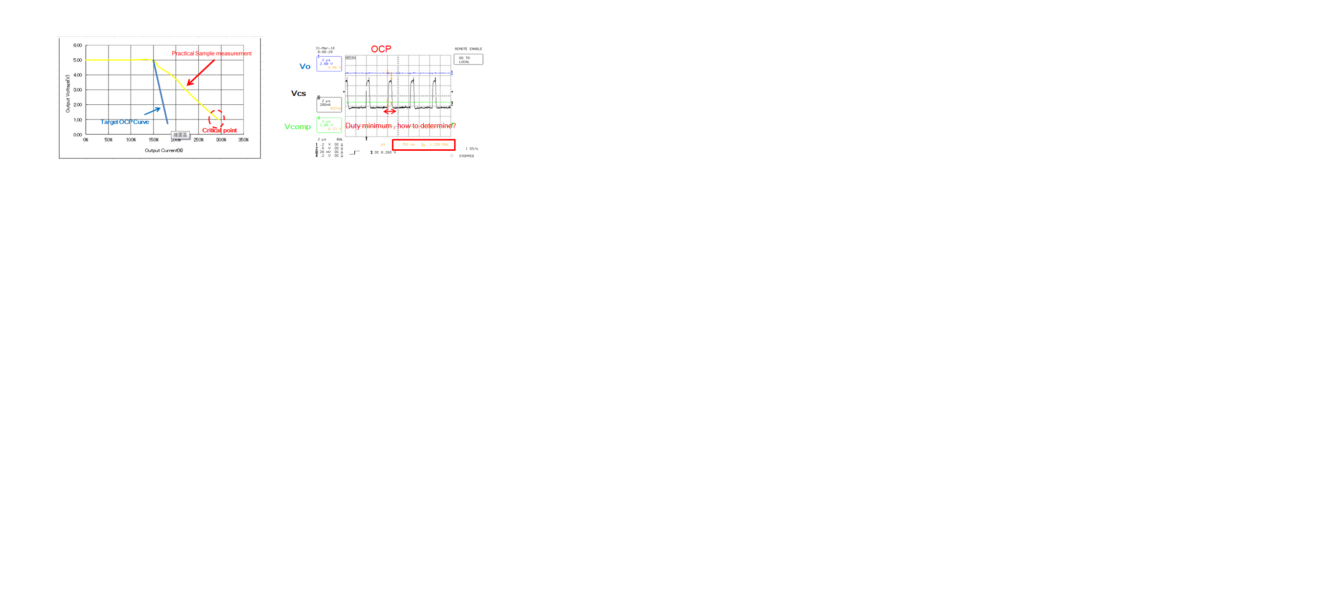
I have a question about LM5025 IC OCP curve.

I use the CS1(cycle by cycle) to limit current , CS2 connect to ground.

When the OCP occurred, the Vo drop , Io increased.

So, how to adjust the OCP curve slope? in this time , the Duty minimum how to determine?

I appreciate your great help in advance.

Best regards,


  • Hi Lewis Cheng,

    The OCP1 function limits peak primary current. It will not provide constant output current for at least two reasons:

    1) There is an error between cycle average inductor current and peak inductor current due to the current ripple in the inductor. The ripple amplitude changes with duty cycle which is a function of output voltage. In other words the error between peak and average inductor current changes as the output voltage falls. It will also vary with input voltage.

    2) The magnetizing current is included in the peak primary current and gives a second error between peak primary current and the output current. This error also changes with duty cycle and therefore changes with input and output voltage.

    The minimum pulse width should be the sum of LEBs interval (50ns) and OCP1 - DRV delay (40ns) giving a total of 90ns. This should limit your minimum duty cycle depending upon your oscillator frequency.

    Thanks

    Joe Leisten