This thread has been locked.

If you have a related question, please click the "Ask a related question" button in the top right corner. The newly created question will be automatically linked to this question.

LM2592HV: Self-built Power over Ethernet switching supply

Part Number: LM2592HV

Hello.

I developed a device that can be operated by 24V as well as Power over Ethernet.

Power consumption is 1.5-2A (peak) at 5.0V, so I decided to take a LM2592HV-5.0.

I produced 50 prototypes and all of them worked perfectly with 47uH inductor.  Now I started series production and almost every LM2592HV is immediately damaged when the device is connected to PoE, while it works fine at 24V DC.

Reading the datasheet very carefully, I noticed that care must be taken special care on the inductor when the operating voltage is above 40V.  This is the case when PoE is used, then 48V is normal.  So I finally increased the inductor to 100uH. This should now definitely be more than sufficient. I also added a TVS diode to the input capacitor to ensure that the voltage never will exceed 55V (still 5V in spare).

Still, it happens in 9 of 10 cases that the LM2592HV dies in fractions of a second on PoE.

Hope that somebody can help me. At the moment I do not really need PoE, but it would make life much easier.

I made a screenshot of the schematic:

A short description, at the beginning only 25k are connected in parallel to the PoE supply. This is the required resistance for specifying Class 1. Only when the input voltage rises to 48V (before I cannot connect such high load or the PoE supply with shut off), the MOSFET is enabled. Now the entire switching supply is powered up and starts working.  As 24V will not trigger the mosfet (-> 24V Zener diode), JP3 has to be closed for operating the device on any input voltage in range of 12..40/60V.

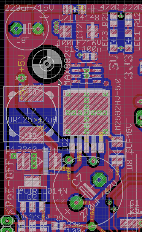
Here is the screenshot of my PCB layout. Blue is bottom side, red is top side of two-sided PCB:

Because I need 5.0V and also 3.3V (with only 100mA), I use a low drop linear regulator (MAX882) for making 3.3V from 5.0V. In the layout you find the 47uH inductor I used in 50 prototypes. I replaced it with 82uH and also 100uH, this made the situation slightly better, but still far away from reliably working without a damage on the LM2592HV.


I hope that somebody can help me fixing the problem. I see no fault in my design.

  • Rainer,

    Thanks for reaching out. That is a high failure rate and a dramatic mode of failure. Let's find out why.

    You said it works at 24V. Can you slowly ramp VIN from 24V to 48V and monitor the 5 pins. Make sure nothing is exceeding absolute max.

    -Sam

  • I am currently working under time pressure, have to finish a first order. At this moment I am finishing it (5 pcs are left), I will repair sorted-out boards from production for it.

    I will make a solder joint instead of the jumper, so no one can accidentally remove the jumper.

    When this first order is finished and delivered, I can take one board from over-production and play with it. I have to fulfil the order first.

    I understand what you want to find out. You want to see if this damage happens by a too fast voltage increase or by the voltage itself.

    The capacitors I use right now are possibly important:

    Input capacitor ... Electrolytic 220uF/100V (Chong, CD11X)

    Output capacitor ... Electrolytic 220uF/16V (Rubycon)

    The LM2592HV-5.0 was bought from a reliable source in China. You find a picture of what is printed on it below.  Hope this is no cheat product (that my supplier was cheated by himself). My supplier sold it at 100% new and original.

  • Rainer,

    We recommend acquiring TI parts through authorized distributors. We can't guarantee a working product if we're not sure if what you have is actually our product.

    That said, yes please let me know when you have the time to play around with a board. Let me know what you find. :)

    Thanks,
    -Sam
  • Hi, Sam.

    Meanwhile I finished the first quantity of ordered parts, so I have some time now.

    You suggest that I slowly ramp up the voltage and see what happens. I will do that using my lab-powersupply. It is the only one able to give that high voltage.

    What is better for power-on?   Slowly rising input voltage or quickly rising one?
    As you can see in the schematic I already supplied, I use a capacitor on the mosfet gate. It will already reduce the speed of turning on the mosfet. If slower powerup is better, I can try to find a way to use a tantal cap instead (but there is not much room at all). Then the mosfet will turn on slower, of course heating up more then, but if this helps, it is ok. It is one powerup cycle, then the mosfet can cool down again.

  • Rainer,

    My thought is to turn on at 24V, then keep it on and slowly ramp up to 48V. Check the pins to see if any abs_max specs are violated.

    If it works at 24V but gets damaged at 48V (and the issue is overvoltage), we will see overvoltage somewhere between 24VIN and 48VIN.

    -Sam
  • Hello, Samuel.


    I will try that.  The major problem I see is the measuring.  Is a normal digital multimeter sufficient, or will I need an oscilloscope?
    As this is a switching regulator, I expect more or less everywhere high frequent switching signals.

  • Rainer,

    You will need an oscilloscope for these measurements. Let me know what you find.

    -Sam
  • Hi, Samuel.


    It is a bit problematic to me, but I will try to do that. The problem is: each try means one damaged 2592HV, another de-soldering and re-soldering, ...and all this causes in shortest time a lost PCB, too. So it is reasonable that I want to reduce this fail-tries as much as possible.

    I will try to set up a PCB with exactly the same capacitors I used in first 50 units. They are a bit different in shape and values. Perhaps this solves the problem, then I know that the 2591 is sensitive on them. I was buying capacitors with very low ESR at the beginning, while the current capacitors look very normal. Can this possibly be the difference?

    I have no experience about the sensitivity of this 2592HV. Does it tend to possibly start wild oscillations, in turn causing over voltages that damage it?
    As the only real difference is the input capacitor, I will give it a try and take one of my first caps. And I will order a few pieces  locally to see if there is any difference.

    The old input capacitor (of first 50pcs series) is:
    Panasonic  270uF/63V   ø16mm x h=15mm (Also has written 105°C [M]CE FC )

    The current input capacitor is:
    Chong 270uF/100V  ø13mm x h=21mm  (Also has written CD11X  -40-105°C )

    Output capacitor on first series was:
    FP 3YAa 221 (so 220uF) 10 (10V)  ø10 x 13mm with strongly sealed can.

    But I also used other ones without any issues.

    Output capacitor now is:
    220uF / 50V  ø10 x 13.5mm

  • Rainer,

    I understand damaging boards and ICs is time-consuming. Try setting VIN=24V and check all the pins. Then try VIN=26V... up to VIN=48V.

    Regarding the capacitors, did the board work perfectly at 24VIN and 48VIN with the original capacitors? If the capacitors were the only change from a working board to a not-working board, that may be a clue as to what's going on.

    This IC does not have soft start. This means the turn-on inrush current will be higher than other converters with soft-start. This will increase the chance of overshoots/ringing on the input/output depending on the system (supply, layout). You can try VIN=24V and toggle the ON/OFF pin and observe the pins of the IC to see if anything is overshooting/ringing.

    I should have noted, the LM2592HV has an ON/OFF pin which can use 2 resistors to serve the same functionality as your zener diodes and MOSFET circuitry. You can set the IC to enable at a certain VIN (and add a jumper to adjust this value). See, "Delayed start-up" in the datasheet.

    Please also order some ICs from a TI authorized distributor or from TI directly on store.ti.com. I want to make sure you we're testing a legitimate TI part.

    -Sam

  • Hi, Samuel.

    Today I have time to work on the board. I will start with using the same caps used on working boards on my experimental board If that works, I save a lot of time, then I know which parts caused the problem.


    According to power source and on/off control pin ...
    It is in the nature of PoE that it does not allow more than 1uF and a resistance different to ~25k at startup. Means, that the input voltage is increased by the power source in three steps:

    1. Apply ~10-12V and measure the current through the connected device. This was the power source is sensing roughly the existence of 25k. This also explains why no big capacitor is allowed at that moment, it would cause false readings. When no valid resistance is detected, the Power-Source stops the process.
    2. Increase the voltage to ~24V and repeat the measurement of the resistor. Because of the higher voltage this can be done more precisely now. Now it depends on the measured resistance which maximum current is sourced by the Power-Source. I use 25k, this means Class 0 (=maximum power).
    3. When the class was negotiated and still everything is in range, the Power-Source increases the voltage to ~48V with current limitation according to the negotiated class. Now the device can pull power the first time.

    This explains why I use this 24V Zener + MOSFET in the schematic at the beginning of the conversation. I use the MOSFET as low-side-switch, causing no load to the Power Supply by itself during startup (the Zener is not conducting at 10-24V). Because of the Zener diode, it connects the entire load (including the input capacitor of LM2592HV !) to the supply when the voltage exceeds 25-26V, this is after the negotiation has finished. I cannot really use the on/off pin and already have the LM2592HV connected because of the limitation to 1uF max, which is far below the requirements of LM2592HV.
    So the voltage on input cap will then rise rapidly to 48V (approx.) while the LM2592HV starts its operation when the MOSFET starts to be conducting.

    All I can do to reduce the inrush current is slowly activating the MOSFET. This I can do with a bigger gate capacitor. Then the MOSFET will heat up for a moment (because it is slowly activating), but act as a series resistor for that time and limit the current. But there is not much time for that, an SOT223-4 package has limited thermal capacity.

  • Rainer,

    Let me know what you find.

    Thanks for that information. I understand now why you need that circuitry.

    -Sam