This thread has been locked.

If you have a related question, please click the "Ask a related question" button in the top right corner. The newly created question will be automatically linked to this question.

UCC28780: Curve fitting time-related Coss

Part Number: UCC28780

Hello Ulrich,

Sorry to reopen this topic, but I can't reconcile the procedure you gave me with the formula in the "Neutron..." worksheet.

This is from the "Neutron..." worksheet:

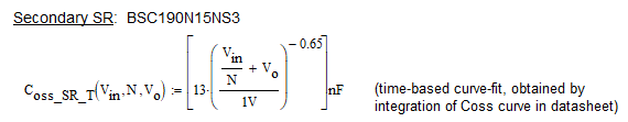
I assume the term in the inner parentheses is the FET operating VDS at which you want to know Coss_SR_T.

I digitized the Coss curve from the FET data sheet and plotted it plus the two versions of time-related Coss, yours and from the formula above:

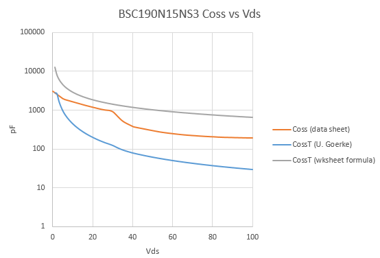
They are significantly different, as you can see.  I'm attaching my spreadsheet with data & computations.  Would you please take a look and see where I'm going wrong?

Thank you! 

BSC190N15NS3 Coss.xlsx

  • Hello Gerrit, 

    There is an error in your column-D equations for D4 through D101.  Instead of Di = SUM(C$3,Ci)/Ai,  it should be Di = SUM(C$3:Ci)/Ai.

    The colon makes a big difference in summing the entire progressive column versus summing just 2 numbers. Making the correction results in the following graph:

    As you can see, the U. Goerke curve now closely matches the wksheet curve for Vds voltages above 20V.  Both of these curves are higher than the instantaneous Coss curve from the datasheet, because the DS curve only plots incremental Coss at a specific Vds.  The time-related Coss is a cumulative value based on the total amount of charge that has to be delivered or removed when the MOSFET voltage changes from one value to another.  Co(tr) is the equivalent non-varying capacitance value that will give you the same resonance time (in an L-C tank) when starting resonant ringing from a particular Vds.  For a device with highly non-linear Coss, the huge charge accumulation at the very low voltages makes teh Co(tr) start out high and stays relatively high, despite the low incremental Coss at high voltages. 

    The work-sheet curve is valid from 20V up, and the error is quite high for Vds below 20V.  That's the nature of curve-fitting where the curve selected fits closely over a limited range of interest.  This is ignorable because we are only interested in Co(tr) at voltage within the actual operating range of the regulator.   For a flyback synchronous rectifier FET, Vds = Vb/Nps + Vo,  where Nps is the pri to sec turns ratio.  We don't care if the curve equation has huge errors outside of the range of interest, as long as it is reasonably accurate within that range.  You do have to know what that range is.  The bottom end of the range of interest is when Vbulk and Vout are minimum, and the top end is when Vbulk and Vout are maximum.   The Co(tr) value to use in a particular calculation is based on the Vbulk and Vout conditions for which the calculation is being done.   

    Please see this file for examples:  Coss(time-based)_BSC190N15NS3_etc.xlsx

    I hope this answers your concern.

    Regards,
    Ulrich

  • Oh, good grief!  I was hoping it wasn't something stupid like that.  I stared and stared at my equations and didn't see the comma where the colon should be.  Thanks for your proofreading.

    Thank you for the explanation of time-related Coss, also.  I had the rough idea that was what it represented, and it's nice to see it spelled out.  This also explains why the time-related Coss is greater than the simple voltage Coss.

    I will repair the other time-related Coss curve-fits in my design, check their range of validity, and press on.

    Best regards,

    Gerrit