This thread has been locked.

If you have a related question, please click the "Ask a related question" button in the top right corner. The newly created question will be automatically linked to this question.

UCC28180: ucc2810 6kw PFC Debugging to assist

Part Number: UCC28180
Other Parts Discussed in Thread: UCC28070

We are using UCC28180 for PFC debugging, and the following problems are encountered:

The output power of the target is 6000W. When reaching 4000W, the PFC current waveform becomes worse and the PF value drops.Please help!

Design parameters:

1. Input voltage range: 187v-254v normal operating voltage: 230V

More than 94% efficiency is required

3. Working power frequency: 45-65hz

4. Output power: 6000W

5. Output voltage: 370VDC

6.PFC inductance: 0.55mH

7. Typical output capacitance: 930uF*3=2790uF

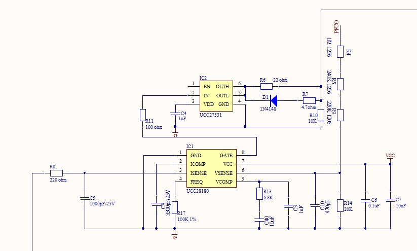
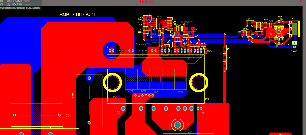
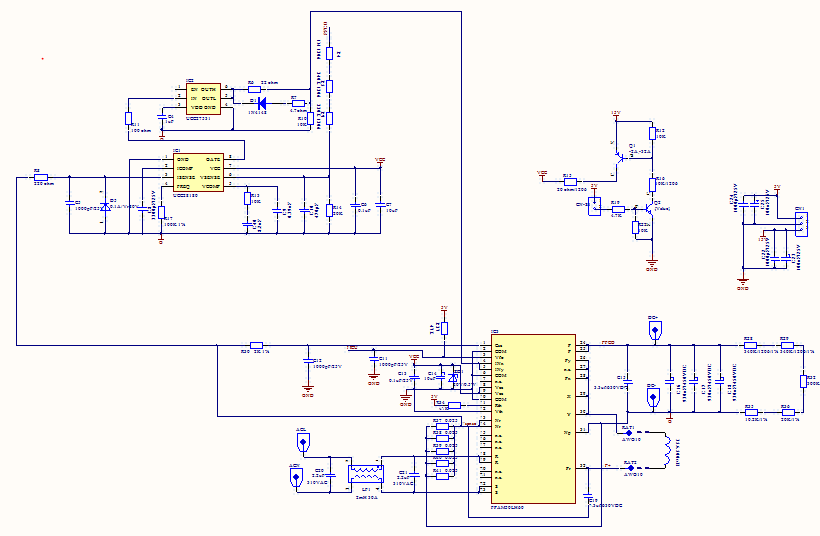
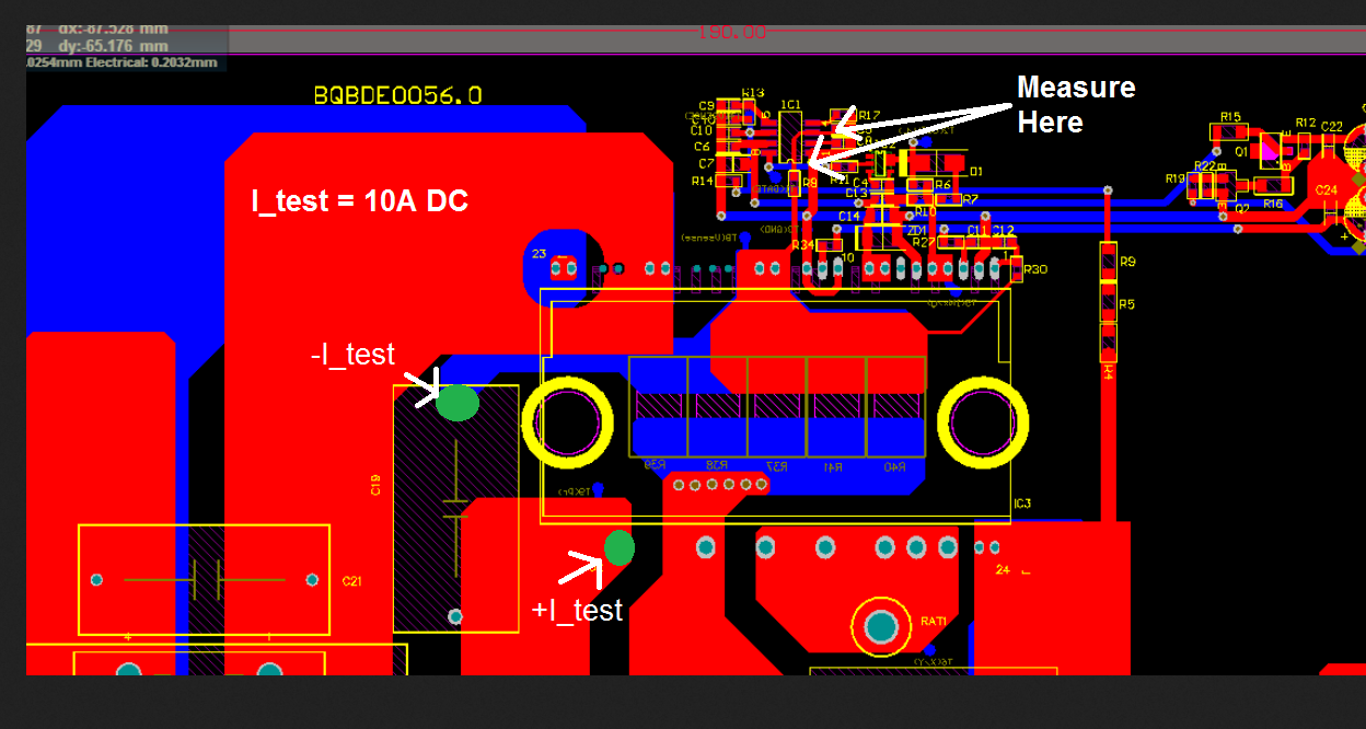
Design circuit diagram and parameter selection are as follows:

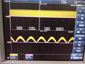
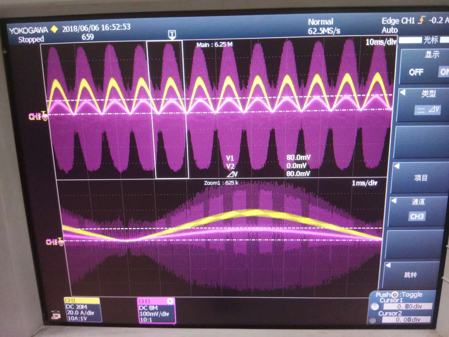
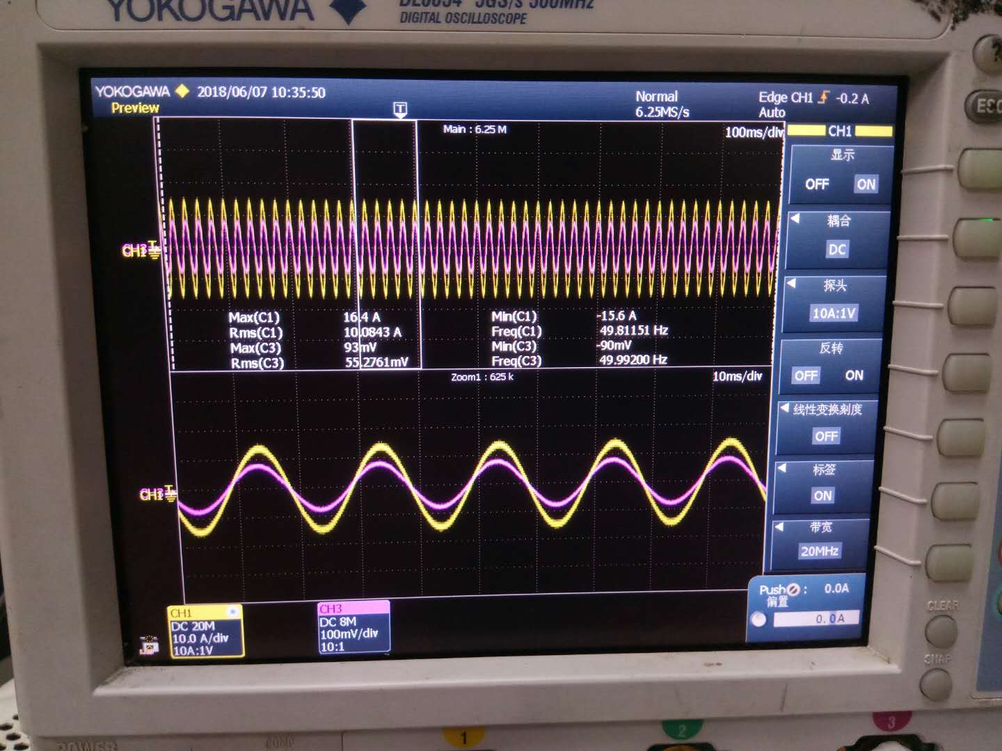
AC 200V input load 3000W, inductance current waveform:

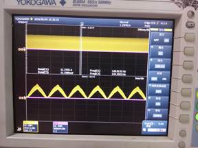
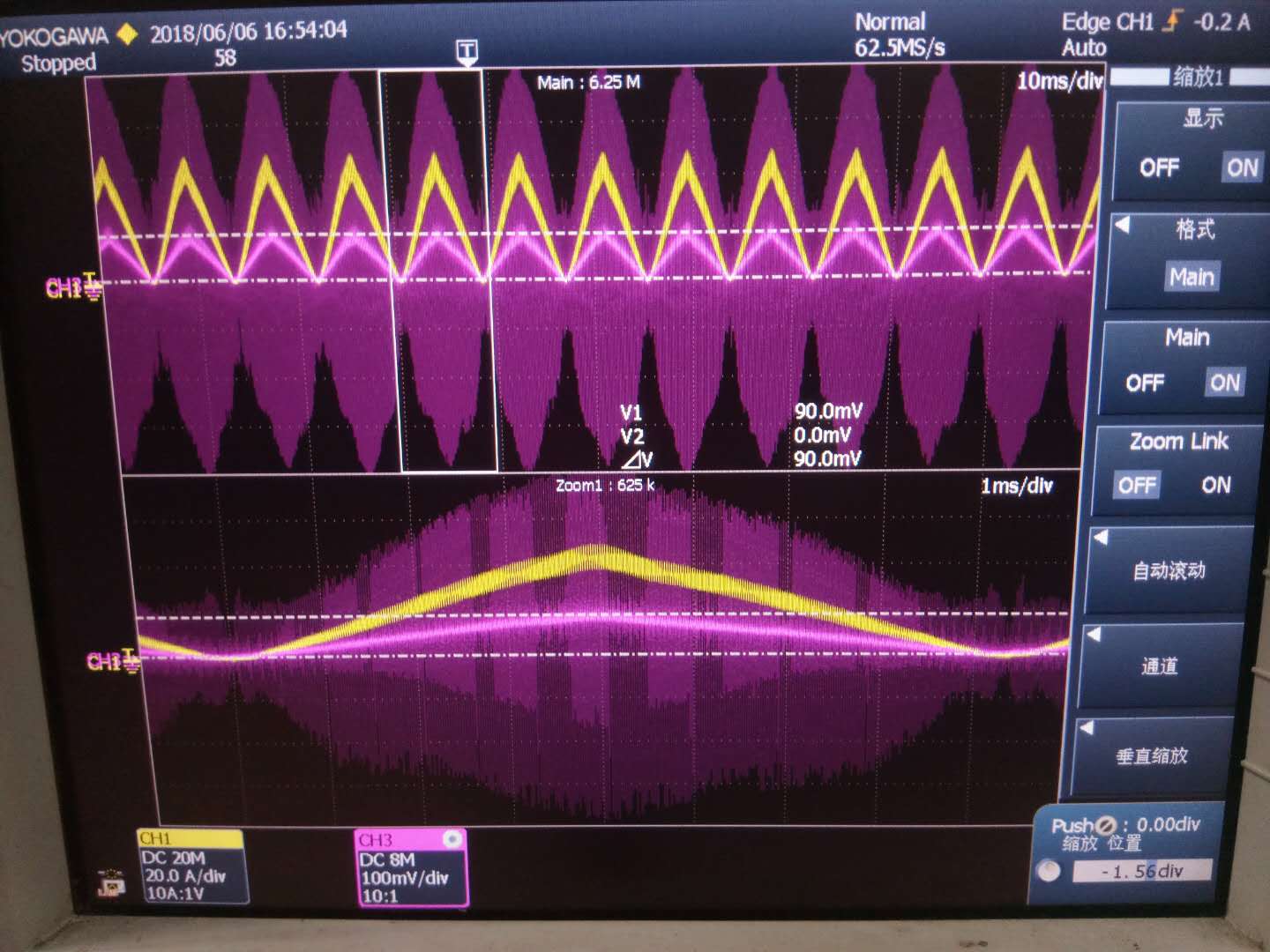
AC 200V input load 3200W, inductance current waveform:

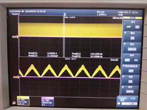
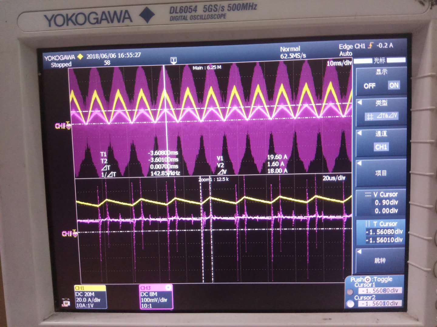
AC 200V input load 3500W, inductance current waveform:

  • Hello

    I think that the problem is that the current sensing resistor is not the correct value. The correct value is given by the device Excel calculator. This assumes a universal input voltage range of 85V to 264V. If the input range is only 187V to 254V the current sensing resistor does not change from the value calculated for the 85V low line value and it is incorrect to double the value of CS resistor on the basis that the currents at 187V are (approx) half those at 85V.

    The second point I would make is that it may be necessary to add a resistor from ISENSE to GND if there is any possibility that the voltage on the ISENSE pin could exceed -1.1V. this can happen during the inrush current phase when the PFC stage is first connected to the line. If the customer's inrush limiting circuitry can guarantee that the ISENSE pin cannot exceed -1.1V then the diode is not necessary, if it cannot guarantee this then the diode is necessary.

    Regards
    Colin

  • HI Colin:

           Thanks a lot for your reply!

    • The original parameter of  the current sensing resistor was 4mΩ. After get your advice, We change the resistor parameters to 2mΩ by the device Excel calculator. As follows:

    CURRENT SENSE RESISTOR:

    Ideal Value for RSENSE, for 110% Inductor SOC Threshold:

    RSENSE(ideal)

    0.002

    Ω

    Actual Value for RSENSE: Current Sense Resistor:

    RSENSE

    0.002

    Ω

    Inductor Current at Soft Over-Current Threshold:

    IOVERCURRENT_SOC

    129.500

    A

    Power Dissipated in RSENSE:

    PRsense

    11.507

    W

    Theoretical Output Over-Current Inception Point:

    IOUT_OVERCURRENT

    19.289

    A

    Maximum ISENSE Peak Current Limit Threshold:

    IPCL

    219.000

    A

    Resistance of Thermistor at 25°C:

    RTHERM

    5

    W

    Maximum Inrush Current:

    IINRUSH

    71.842

    A

    Recommended ISENSE Series Resistor:

    RISENSE

    220

    W

    Recommended ISENSE Filter Capacitor:

    CISENSE

    2700

    pF

    • Result:
    • The output power can be increased to 4500W.  However, after reaching 5000W, the current waveform will also be abnormal and the PF value will decrease.
    • 4500W OUTPUT    CH1:CHOKE CURRENT   CH3:THE VOLTAGE OF CURRENT SENSE RESISTOR
    •    


    • 5000W OUTPUT    CH1:CHOKE CURRENT   CH3:THE VOLTAGE OF CURRENT SENSE RESISTOR
    • 5000W OUTPUT    Expanded waveform


            We want to know why the current waveform is distorted?

            Our target  is to output  6000W .Do you have any other suggestions?!

            Best regards!

  • Hello Xiaohong

    Part of the problem may be that 2mOhms is a very low resistance and unless the voltage sensing points are located directly at the resistor you can get errors due to parasitic resistance in the PCB. The result is that you may have placed a 2mOhm part on the board but the circuit is behaving as if it were a 3mOhm part (for example)

    I would advise that you check the resistance value the system is seeing - Connect a current source positive at the MOSFET source and negative at the bridge rectifier and run a known current through the resistor - say 10A. It is very important that the current flows in the same path as the switching current does so that the effects of any parasitic resistances are included. Then measure the voltage between the GND and ISENSE pins of the UCC28180 - this is the voltage that the controller uses.

    Please send me a copy of your layout so that I can review it, I prefer Gerber files because they are easier to review. If you can't post it here then send it to me directly at colingillmor@ti.com 

    If you are using a NTC, then I would strongly advise that you include the diode from ISENSE to GND as shown in the DataSheet. The reason is that if your product is running for some time the NTC resistance will be much lower than 5 Ohms. If the line voltage is interrupted for a few seconds, the output capacitors will have discharged but the NTC won't have cooled down so it will still be a low resistance when the line power is restored - you can expect a large inrush current.

    Regards
    Colin

  • Hi Colin :

              We follow your advice today.  " Connect a current source positive at the MOSFET source and negative at the bridge rectifier and run a known current through the resistor - say 10A".

              Then measure the voltage between the GND and ISENSE pins of the UCC28180.

              The current sense resistance is 5mΩ.

              The result  is the difference between actual measured voltage and theoretical calculation is small.

              The picture as follow:

             1.current --15A

              CH1:input current        CH3:The voltage between the GND and ISENSE 


             2.current --10A

              CH1:input current        CH3:The voltage between the GND and ISENSE 


    In our test,we have added  a DIODE between ISENSE to GND to avoid the voltage of ISENSE excced -1.1V.

    As for LAYOUT, since my file is encrypted, I can only send you the picture at present. Please see if you can see it clearly

    We now doubt whether the UCC28180 can achieve the power of 6KW. What do you think?!

    THANKS A LOT!

  • Hello Xiaohong

    The calculator says you need 2mOhm but you are measuring 5mOhm so there is an error somewhere.

    Can you redo the test please because I meant for you to use a DC current so that you can get an accurate 4 wire measurement of the resistance that the controller sees. I've marked up the layout you sent me to show where the 10A current should be injected and where the measurement points should be. If you have 2mOhm then 10A should give 20mV.

    Looking at the layout I suspect that the actual resistance is significantly higher than 2mOhms but let's take the measurement and see.

    It's not clear to me how the GND pin of the IC is connected to the current sensing resistor - I can see a yellow dot at pin 1 which may be a via but I'm not sure. Of course the GND connection is equally as important as the ISENSE connection.

    Could you send me a screenshot  - like the one below - but one for each layer in the board. can you also tell me what thickness of copper you are using on the PCB (1 oz, 2 oz, 35um, 70um etc). This will help me estimate the parasitic resistance of the tracks. See https://e2e.ti.com/blogs_/b/powerhouse/archive/2016/10/03/why-should-i-count-squares for an example.

    We do have customers using this controller at up to 8kW so 6kW is certainly possible. The main difficulty is in guaranteeing a good ISENSE signal because the current sensing resistor is so small. I would suggest we try to diagnose the problem and correct it before making major design decisions. Having said that, it is also possible to design an interleaved PFC stage at this power level - the UCC28070 controller is recommended for this application.

    Regards
    Colin

  • HI Colin:

              I have sended the email to you, because I need to send you the attachment. Would you please check it.

              We are currently debugging in beta, and if successful, it will be immediately applied to the product.

              At present, single-stage PFC is our optimal choice, so we haven't considered interleaved PFC stage yet now.

              For more, please see the contents of the email.

              Thank you very much!

  • Hello Xiohong

    Thanks for the emails and we can continue this conversation via email.

    For the benefit of the other members of this forum the measurement gave a 2.4mOhm resistance. This means that the controller is using 2.4mOhms as its current sense resistor instead of the 2mOhm recommended by the calculator. The difference is due to the parasitic resistance of the PCB.

    The next step is to try to reduce this resistance, as a test we can solder another 10mOhm part across one of the 5 existing CS resistors and this should reduce the resistance seen by the controller to closer to 2mOhm and allow testing at higher powers.

    If this confirms the problem then the next step is to work on the layout to reduce the effect of  the parasitic track resistance.

    Of course one option would be to use 5 x 8mOhm sensing resistors in parallel instead of the existing 5 x 10mOhm and use the parasitic track resistance as part of the CS resistor. This may be ok but copper has a significant temperature co-efficient of resistance and its effect on the total CS resistor value would have to be checked.

    Colin

    Regards
    Colin