This thread has been locked.

If you have a related question, please click the "Ask a related question" button in the top right corner. The newly created question will be automatically linked to this question.

TPS62421: 1.8V Regulator High Output Voltage

Part Number: TPS62421

I am using a fixed default output part (TPS62421) to generate 1.8V and 1.2V rails for a system.  In certain low load scenarios I'm seeing the 1.8V output go unexpectedly high, up to 2.4V.  I'm looking for any suggestions as to what might be causing this and recommended fixes.  One thought is the MODE/DATA pin is tied high in our circuit, could operating in forced PWM mode cause such an over voltage in low load scenarios?

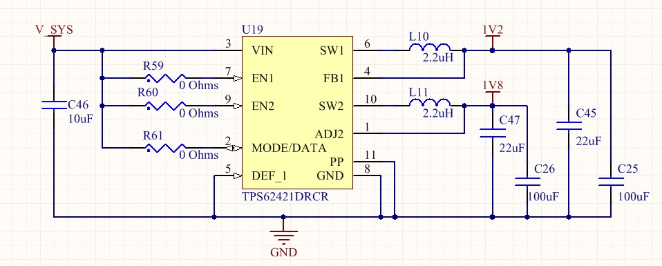
Below see a circuit diagram, a brief description of the problem, and an annotated scope plot showing this sequence.

  1. When I first power the system on it's held in reset and has a low current draw (~100mA), during this time I see the 1.8V output at approximately 2.4V. 
  2. When system reset is released current increases to ~400mA and output voltage comes down to 2.1V.
  3. When system input voltage is reduced from its nominal value of 3.9V down to 3.1V I see the output voltage finally go to 1.8V, reduction of input voltage below 3.1V results in the output staying constant at 1.8V.

  • Hello Zachary,

    It's my pleasure to support you.

    Your input voltage seems behaving quite weird, so I would like to understand if it is an effect or could be one clue for determining the cause of your problem. Hence the questions:
    -how is Vin generated?
    -at which point are you probing it?

    Another thing I noticed is that you are using 100 uF caps in parallel to the 22uF recommended by the datasheet. Too much output cap may cause misoperation of the feedback loop.
    -Could you try to remove them and share the waveforms? Rather than the input current, do you have the possibility to measure the load current instead, both will be the best?
    - What do you have connected to the 1.8V node and what is the load exactly supposed to be?
  • Hi Emmanuel, thanks for the response. I'm away from the lab today so will have to try the hardware changes you recommend later.

    Vin is generated by interfacing our system with existing hardware which we have no control over. That's the cause for the very slow ramp up and odd behavior when the system is off. The existing hardware has a trim setting that is user adjustable, that's how I dropped the voltage at the end of the wave form, however the intent is to leave the trim setting at maximum at all times. I believe the same over voltage occurs when using a bench top power supply, but I'll verify this with scope plots. I'm probing Vin right before the input to the TPS62421 regulator.

    I'll also try removing the 100uF caps to see if excess capacitance is causing this. I can get the 1.8V current draw too, but it might have to be one or the other, not sure I have access to a second clip on current probe. The 1.8V node powers a microcontroller, a FPGA, RAM and various associated components. I expect load to be in the 500mA range, but as software changes so does current draw so the exact load hasn't been completely pinned down.

    -Zach