This thread has been locked.

If you have a related question, please click the "Ask a related question" button in the top right corner. The newly created question will be automatically linked to this question.

TPS63010: high inrush current causing regulator to enter a bad state

Part Number: TPS63010
Other Parts Discussed in Thread: TPS2553, TPS25221

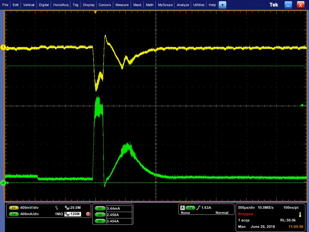
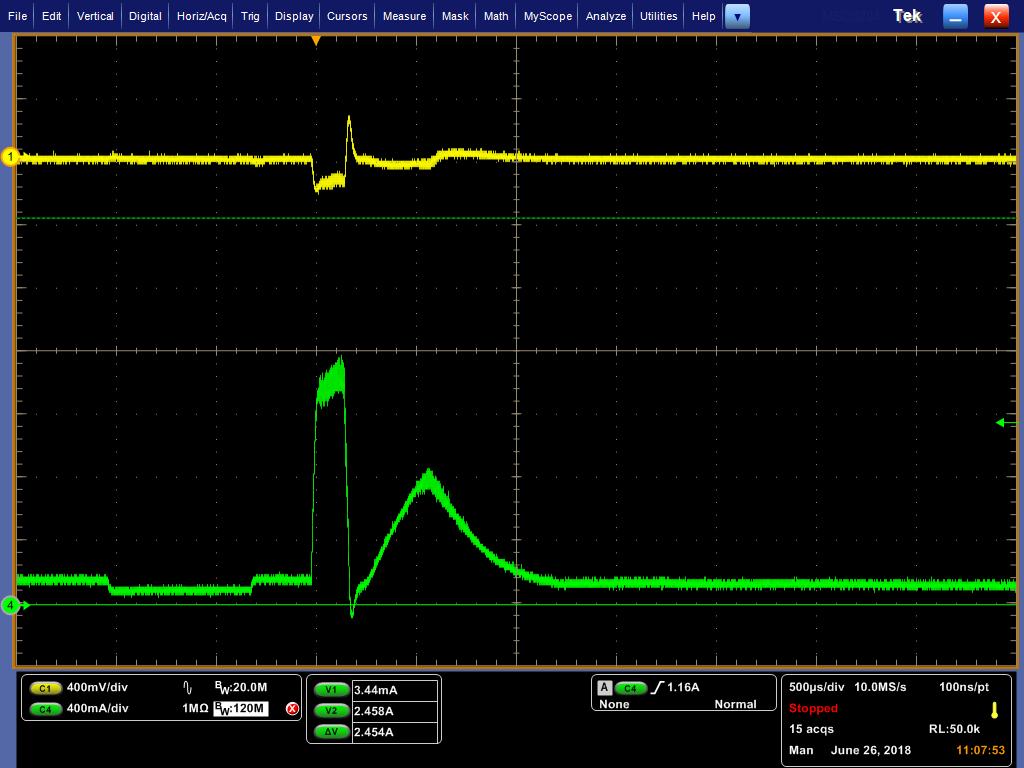
The TPS63010  circuit provides power to our product which has an LED to provide lighting. When the LED is turned on there is a high inrush of current. After a high inrush of current this regulator goes into a bad state where the voltage drops to about 2.4V, The AC coupled ripple voltage, the input current and the output current are shown below when in this state.

 Is there anything we can do to keep from going into this state?

Attached is the schematic of this part. I also tried removing D1, R7 & C20 and changed R9 to 97.6k to get a 3.3V output

One more thing of note is that we have a current limit switch TPS2553 feeding the input to the buck boost regulator.

TPS63010 schematic.pptx

See attached

  • Update- From the customer


    We removed the TPS2553 and shorted input to output. The scanner now works as expected. We also tried increasing the current limit of the TPS2553 but that did not work. We still don’t understand why this is happening.
  • Hello Robert,

    Thank you for the update. So when they short the current limit switch the system is working properly?
    Are L12 and L3 still in the system when they short U14?
    As the customer tested different circuits, which one is the one used at the moment.
    Please measure the inrush current when the load turns on. It would be good to get as well the load connection.

    Best regards,
    Brigitte
  • Hello Robert,

    There is one point that I observed on the schematic: It seems that you are using a Schottky diode in the softstart circuit. The softstart circuit needs a silicon diode similar to 1N4148 to operate properly during VIN startup.

    In general it is possible that TPS2553 limits the inrush current the way that the input voltage on TPS63010 is reduced to a level where the IC gets stuck in the startup. It is possible that this happens in your system.

    Best regards,
    Brigitte
  • In the original post. I stated that I removed the soft start circuitry and the problem still occurs.
  • The TPS63010 is on and running when this high current inrush occurs so I doubt it is stuck in startup. My thinking is that the input voltage drops enough during the inrush causing it to switch from buck mode to boost mode. This quick transition is causing the TPS63010 to get in this bad state.
  • Taking the enable pin low and back high clears this issue.
  • Hello Steve,

    Thank you for updating.
    The softstart circuit will not have any effect, if the inrush current happens during normal operation.

    Please measure the input voltage during the inrush event. I expect that the input voltage drops and the part is going into boost mode, at the same time the TPS2553 limits the input current enough that the voltage does not rise again and the TPS63010 stays in boost mode. As the switch current of a boost converter needs to be higher than of a buck converter (at the same load), the device is not able to rise the output voltage again because of the switch current limit and the current request of the load. This means that the system is stuck in this mode, not the IC.

    To have a detailed look at this, it would be necessary to measure the input voltage of TPS63010, the inductor current and the output voltage at the moment when the load is enabled.

    Best regards,
    Brigitte
  • I have tried removing the load after entering this state. That did not get the TPS63010 out of this state.
  • Input

    Output

    We changed the TPS2553 to a TPS25221 that is set up for a 2.3A. The TPS63010 works fine in this configuration. There is still a large droop on the input voltage when the inrush of current occurs. Attached are 2 oscilloscope traces for input current/voltage and output current/voltage.

  • Brigitte- has there been further follow up on this?

  • Hello Steve,

    Please excuse the late response.

    Is the use of TPS25221 possible in your system?

    Ok, so we know now that the combination inrush current limit plus TPS63010 is not working. It is interesting that removing the load does not recover the TPS63010. We will try to reproduce this in the lab.

    You could try to reduce the input voltage drop by adding more capacitance on the input and therefore reducing the input impedance. Normally the output voltage drop should then be somewhat reduced as well. Additional capacitance at the output should help here as well.

    Best regards,
    Brigitte
  • We are planning on switching to the TPS25221 in our system. We could switch to a 22uF capacitor instead of 10uF on the input of the TPS63010. This is as big as we can go with the current layout that has 0603 pads on both the input and output capacitors.

  • Steve,

    We have a question to clarify about your LED driving circuit. I'm not sure this is affecting the behavior you're seeing, but one of our engineers noticed your schematic doesn’t have a current sense to ground shown.  The FB is voltage feedback, not current feedback- at least as we're interpreting it. Are we missing something?

    RobTPS60301 schematic questions.pptx

  • Rob,
    I'm not sure I understand the question. The 3.3V output from the TPS63010 is used to power a boost circuit that powers a bright LED. We use voltage feedback in our circuit for the TPS63010.
    Steve
  • Hello Steve,

    Do I understand correctly that with changing to TPS25221 the problem is at the moment in your system solved?
    If not, there are some more tests that might be possible, but this would be again a change in your system:
    - More input capacitance on TPS63010 (maybe even more than you can fit at the moment just to check if this could be a solution)
    - More output capacitance on TPS63010 (although I expect this will not help a lot)
    - Softstart of the load. You mention that there is a boost circuit connected as load to TPS63010, would it be possible to start this one slower?

    My plan is to order TPS2553 and check if I can reproduce the problem you observed (that the device gets stuck somehow), but this will take some time. Would you share the boost circuit and the load you have for closer test circuit?

    Best regards,
    Brigitte
  • I have not see the TPS63010 go into the bad state since replacing the TPS2553 with the TPS25221. I do not have access to the boost circuit. It is part of a module. Right now we are hoping to get software to allow the boost circuit more time to charge before the LED illuminates.
  • Hello Steve,

    Thank you very much for your feedback. I interpret your answer the way that you are ok with using TPS25221. Is this understanding correct?

    Best regards,
    Brigitte
  • It is disturbing that the TPS63010 got in this state and the only way to get out of the state was to reset the chip but yes we are moving forward with the TPS25221.