This thread has been locked.

If you have a related question, please click the "Ask a related question" button in the top right corner. The newly created question will be automatically linked to this question.

TPS22929D: Reverse voltage protection not working under certain circumstances

Part Number: TPS22929D
Other Parts Discussed in Thread: TPS22917

Hello,

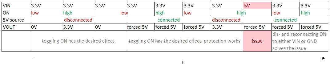
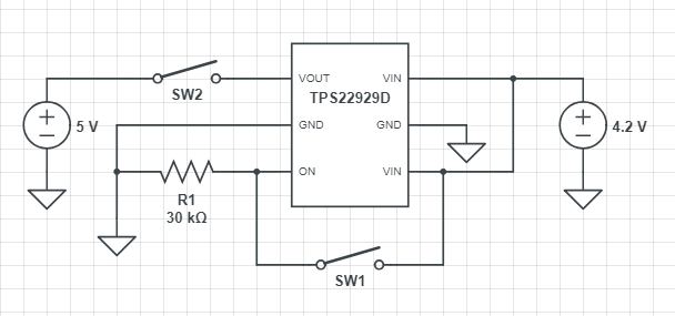
testing the TPS22929D Load Switch I found out that when I permanently connect the ON-pin to VIN (circuit is as shown in the datasheet with caps. etc.) the reverse-voltage protection doesn't work.

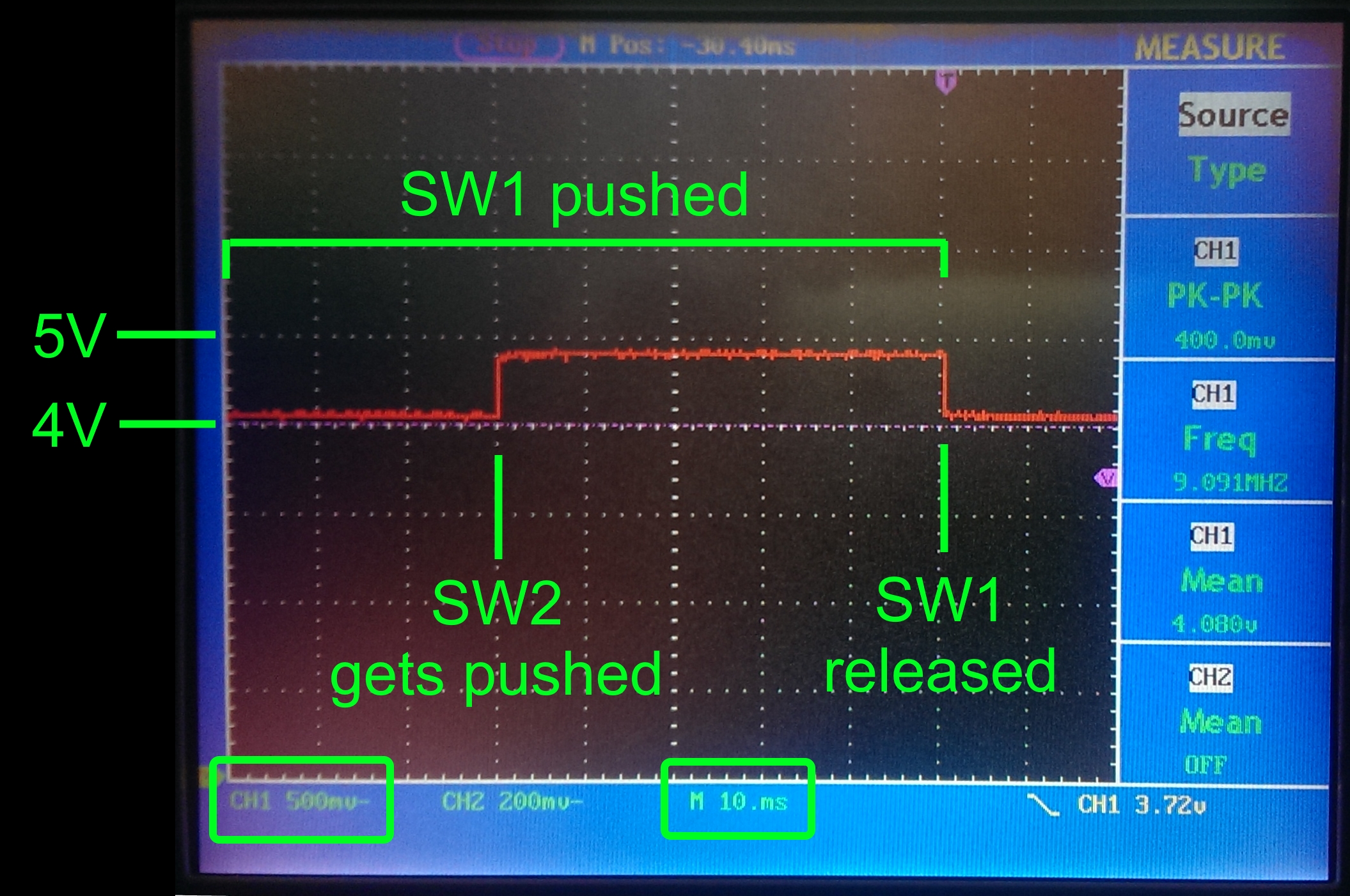
VIN is connected to a Li-Ion 3.7V battery pack. When I connect a 5V power supply to VOUT the voltage on VIN is higher than before. Connecting ON to GND or dis- and reconnecting ON to VIN after the problem occurs the IC works as intended and VIN is as expected. So the issue only exists when ON is already connected to VIN when the 5V are applied.

What could cause this issue and is there a workaround?

With kind regards,

Daniel Ulrich

  • Hi Daniel,

    If 5V is forced on VOUT and 3.7V is forced on VIN, then reverse current blocking should be active. The device would be able to detect this voltage difference and shut itself off. Is this only happening when the 3.7V source on VIN is disconnected?

    Thanks,

    Alek Kaknevicius

  • Hello Alek,

    thanks for your quick response.

    Yes exactly, that's what I want it to do. Normally the feature works perfectly fine (e.g. when ON is connected to GND or connected to VIN after 5v are applied on VOUT). Only when ON is already connected to VIN before 5V are applied. The 3.7V source itself is permanently connected to VIN.

    Regards
    Daniel
  • Hi Daniel,

    When the 5V and 3.7V sources are applied to VOUT and VIN (respectively), do you measure a voltage drop of 1.3V across the device? Also, does it turn off at all?

    Thanks,

    Alek Kaknevicius

  • Hi,

    the device turns off when ON is connected to GND (this works without exceptions). When 5V are applied (while ON is still connected to GND) and then ON is connected to VIN it also works alright (device blocks reverse-current). Only in the described case when it's the other way round and ON is already high when 5V are applied there is this strange behaviour. As I said: Disconnecting ON in this case immediatly solves the issue. ON can than be connected to either GND or VIN and the voltage on VIN is ok from then on.
    I assume that the voltage drop between VOUT and VIN is nearly zero in my error-case and only the Li-Ion internal battery-protection is preventing it from rising higher than 4.2V. I just connected the Arduino-Uno boards 3.3V output to VIN and after making the same test the measured voltage on VIN is 5V instead of 3.3V. Dis- and reconnecting ON again solves the issue.

    I used the TPS22929D in several projects without any issues. But testing it in a new application I ran across this problem.

    Regards
    Daniel

  • Hi Daniel,

    It sounds as you've described, that with the 5V source and 4.2V source, one source is preventing the other from keeping its voltage. Without this voltage across the device, the device will not be able to enter its RCB state while ON is high. Do you have any scope shots of the 5V source being applied? It would help to see what VOUT and VIN are doing.

    Also, we do have a next gen version of this device, the TPS22917, that has a lower voltage threshold from VOUT to VIN for RCB activation. Perhaps a device like this may work better at detecting the voltage difference.

    Thanks,

    Alek Kaknevicius

  • Hi,

    the voltage sources should be decoupled and don't have an influence on each other as the 5V come from a USB wall adapter and the 3.3V / 3.7V from other sources. As I don't have access to a scope right now I attached a file where I show the testing procedure and its results in a table from left to right.

    You can see that the voltage on VIN in issue-case is 5V, but it should be 3.3V as VIN is always connected to 3.3V. Note that the issue is solved as soon as ON is disconnected (floating). From then on it can be connected to anything without any problems. I just can't see the reason for it happening. Obviously the IC works as intended in every other case. And because it works in every other case I think we can rule out that it has something to do with the voltage difference or thresholds.

    Regards

    Daniel

  • Hi Daniel,

    Thanks for the detailed table. It looks like the forced 5V source on VOUT is pulling up the voltage on the 3.3V source to prevent any voltage drop from VOUT to VIN across the device. It also does not seem to take a significant amount of current to do this, because with enough reverse current the device would still enable RCB. When the 5V source is forced on VOUT, and the 3.3V source on VIN is being forced higher, how much current is passing from the 5V source to the 3.3V source?

    Thanks,

    Alek Kaknevicius

  • Hi,

    First of all, here is my testing circuit:

    I removed the capacitors on VIN and VOUT to remove their discharge curves in the measurements (the sources are pretty stable by themselves). Further I again swapped the VIN-source to the Battery because the 3.3V source has build in capacitors and I again don't want to have their influences on the measurement.

    Now I got some scope-shots from what VIN is doing:

    It shoots up straight when VOUT is froced 5V. After SW1 is released the circuit is in the state when everything is ok. Toogling SW1 from then on has no difference and the voltage stays at a stable 4.2V in every case. I believe that in the error-case current is near 0A because both voltages are equal, so the device is not capable of detecting a reverse voltage case and thus it doesn't do anything against it. This would answer the question why it isn't shutting down. But what's not explained is why VIN can climb up to 5V in the first place.

    I assume that inside the device there are unwanted reverse-currents pulling VIN up to 5V before the internal measurement is taken. It's the only plausible cause for me right now. Could it be that the device has a major general error build in causing this? Btw: I already swapped ICs in the test to rule out that it is a broken testing-device.

    Regards

    Daniel

  • Any new idea for this case?

  • Hi Daniel,

    Based on the description and scope shot, I think the device may be acting normally. When the device is ON, it acts like a very small resistance, so it will connect the 5V and 4.2V supplies together. The 4.2V supply seems to be very weak, because the 5V supply is able to force it up to 5V as well. The amount of current from the 5V source that is needed to do this must be less than the threshold for the device to enable reverse current blocking.

    Thanks,

    Alek Kaknevicius

  • Ok, I understand the problem with that.

    So in order to protect the lower voltage power source it would be best to use an ideal diode instead or additionally to the power switch? Or is there any other device doing the job?

  • Hi Daniel,

    The cleanest way to do this would be to somehow turn the switch off when the 5V source is connected, but this would require additional logic. I have reached out to our ideal diode applications engineer to see if there is a part he would recommend.

    Thanks,

    Alek Kaknevicius

  • Hello,

    thank you!

    Yes I already tried a logic with an op-amp across the power switch do determine in which direction current is flowing through the device (in which direction the (very) small voltage drop across the device is). That worked as expected, but it's not the cleanest way of doing the protection and requires additional space and parts.

    Regards
    Daniel