This thread has been locked.

If you have a related question, please click the "Ask a related question" button in the top right corner. The newly created question will be automatically linked to this question.

TPS3801: TPS3801K33DCKR

Part Number: TPS3801
Other Parts Discussed in Thread: TPS3103, TPS3808, TPS3803

Dear SIR:

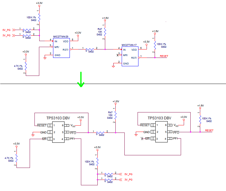
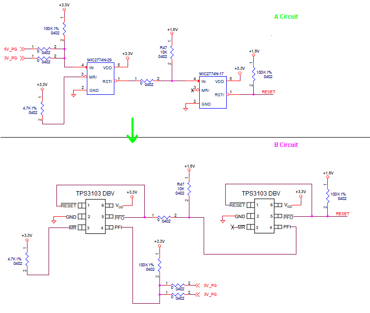
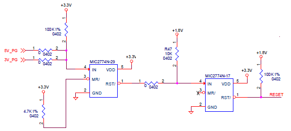
May I double confirming TI have any product can replace the part as attached ( http://ww1.microchip.com/downloads/en/DeviceDoc/mic2774.pdf ) ?

EX:TPS3801K33DCKR can  replace the part as attached ? Or Would you have any recommend TI  product for  replace the part as attached.

We application on attached circuit.

Thanks

  • TAlex Wu,

    We have a few options to replace this device. If the device is only monitoring 4V or less, a good replacement is TPS3103

    http://www.ti.com/lit/ds/symlink/tps3103.pdf

    This device monitors voltage via VDD and PFI and there are two independent outputs RSTSENSE and RSTVDD. If you want one single output, RSTSENSE and RSTVDD can be tied together. This device also provides manual reset.

    If a single voltage monitor is OK, TPS3808 is a good option.

    http://www.ti.com/lit/ds/symlink/tps3808.pdf

    Please provide feedback on key must haves if these devices will not work. Thank you!

    -Michael

  • Dear SIR:

    Thanks for your reply.

    May I double confirming" Is that your meaning detail as below for TPS3103 Dual power monitor ?"

  • That is correct replacement. I have a couple questions for the circuit:

    1. Why is PFI on the first device only have a pull-up resistor? This is not the typical configuration and this will only trigger a reset if "5V_PG" or "3V_PG" fall below 0.551V. This is OK if this is expected.

    2. Why does /MR on first device have a pull-up resistor? If this /MR is not being used, the pin can be left floating saving one resistor cost.

    3. Is there a reason why /PFO pulls up to 1.8V and not VDD = 3.3V? This is OK but I am curious why this is chosen.

    -Michael

  • Dear SIR:

    Thank for your reply.

    But,May I double confirming "Is your "couple questions " for "Original Circuit [A circuit] " or "after replace to TPS3103 circuit  [B circuit]" ?


    If your "couple questions " for "after replace to TPS3103 circuit  [B circuit]" .

    Is your meaning:

    (i) "When MIC2774N-29 and MIC2774N-17  [ [A circuit]] change to  "TPS3103"  [B circuit] " that  "peripheral circuit" will different [keep Original peripheral will  incorrect] ? or ...?

    (Sorry , I have confusing . because you reply "That is correct replacement." ,but have  "couple questions ")

    Or

    (ii) your meaning "couple questions " only for  "Original Circuit [A circuit] " . [  "after replace to TPS3103 circuit  [B circuit]" function and "peripheral circuit" the same  "Original Circuit [A circuit] " ]

    (iii) Or...?

    Thanks

  • Yes that is the correct replacement. But the original schematic didn't seem to be the typical configuration how both MIC2774N or TPS3803 is normally used.

    Typically, the "IN" pin for MIC2774N and the "PFI" pin on TPS3803 use a resistor divider to set the trigger voltage. In both schematics, there is a single pull-up resistor. Although you have correctly replaced the device, I do not see these devices used this way. I would like to get a better understanding of the intended use for "IN" or "PFI" pins to make sure the circuit is working as expected.

    -Michael

  • Dear SIR:

    Thank for your reply.

    May I double confirming:

    (1)Therefore, "your "couple questions " only for "Original Circuit [A circuit] " ,Right ?

    (2)Base on you mention "That is correct replacement",therefore  [A circuit]] change to  "TPS3103"  [B circuit] " that  "peripheral circuit" no need change .

        (Change another word: Is that your meaning "after replace to TPS3103 circuit  [B circuit]"  the same "Original Circuit [A circuit] ",Right ? )

        (Change another word2: Is that your meaning "after replace to TPS3103 circuit  [B circuit]"  =  "Original Circuit [A circuit] ",Right ? )

    ==================================================================================

    As we know the "Original Circuit [A circuit] " is  MIC2774N-29 will issue pin 1 output  when monitor VDD and pin 4 IN =Low ,then  MIC2774N-17 will issue pin 1 output  when monitor VDD and pin 4 IN =Low     [ MIC2774N is "N" Version  ,Open Drain output and Active Low ]

    <5V_PG and 3V_PG  is Open drain pin from 5V and 3V power IC

    5V_PG and 3V_PG is Low for  MIC2774N-29 When 5V and 3V abnormal  or 5V and 3V not ready

    5V_PG and 3V_PG will release (Open drain,pull High by external 100k with 3.3V )for  MIC2774N-29  when 5V and 3V normal  or 5V and 3V  ready>

    MIC2774N-29 is Low for  MIC2774N-17 When 5V and 3V abnormal  or 5V and 3V not ready

    MIC2774N-29 will release (Open drain,pull High by external 100k with 3.3V )for  MIC2774N-17 when 5V and 3V normal  or 5V and 3V  ready

    MIC2774N-17 out pull by External with 1.8V , because "RESET" is 1.8V for END device.

    Therefore, How about  "after replace to TPS3103 circuit  [B circuit]" ? 

    Thanks

  • 1. My questions are for both circuits. Both circuits use a voltage supervisor so I am talking about the typical configuration for both circuits as both circuits have the same functionality.

    2. In both circuits, we typically do not see a pull-up resistor only on the "IN" or "PFI" input pins. Typically we see a resistor divider. The only case where a pull-up resistor only will work on "IN" or "PFI" is if monitoring an open-drain input which you mentioned is the case.

    Very interesting use case. Normally, our devices along with our competitor voltage supervisors monitor an analog voltage input signal. It seems that in this case, the voltage supervisor is monitoring a digital signal (either logic low 0V, or logic high 5v or 3V). This will work, just not typically how we see these devices used.

    For the correct configuration for both A circuit and B circuit, you should use a resistor divider with:

    trigger voltage = 0.551 x (Rtop + Rbottom) / Rbottom

    Have the original circuit A been tested before?

    -Michael

  • Dear SIR :

    Thanks for your reply.

    For the correct configuration for both A circuit and B circuit, you should use a resistor divider with:

    trigger voltage = 0.551 x (Rtop + Rbottom) / Rbottom

    Have the original circuit A been tested before?

    <Reply>==>No,original circuit A  We didn't test before. But ,It is come from main chip reference design . 

                        Base on circuit A  MIC2774-29  table list Vth is 2.93V ,  MIC2774-17  table list Vth is 1.69V  ,IN pin Vref is 300mV

                        "trigger voltage = 0.551 x (Rtop + Rbottom) / Rbottom" seems come from TPS3103 spec.

                        TPS3103 seems different MIC2774 , circuit B "peripheral circuit" will need to change and can't the same  circuit A ,Right ?

                        Therefore regarding  circuit B ,Would you have any advice ?


                        Thanks


  • The TPS3103 has a 2.941V version (TPS3103K33) but does not have a 1.69V version, the closest is 1.523V (TPS3103E16) or 1.843V (TPS3103H20).

    For the PFI pin, the threshold is 0.551V so you use a resistor divider with

    trigger voltage = 0.551 x (Rtop + Rbottom) / Rbottom

    as shown in Figure 16 of the datasheet: http://www.ti.com/lit/ds/slvs363g/slvs363g.pdf

    Please let me know if this is clear.

    -Michael

  • Dear SIR:

    Thank for your reply.

    But,May I double confirming :

    (1) according to your reply:

          Is that meaning as below ?:

           For VDD pin or PFI pin Vref is 0.551V

          TPS3103K33 and TPS3103E16  's VDD pin have "internal resistor divider" therefore base on different sku.(for example: K33 ,E16 ) have different Vth.(K33 ->Vth is 2.941 ,E16 vth is 1.523)

          MR# pin have internal pull up to VDD resistor. 

          But, PFI pin without  "internal resistor divider" ,therefore PFI pin need add external resistor divider for met requirement by  Vth =0.551 x (Rtop + Rbottom) / Rbottom  calculator .

          Therefore ,

                            TPS3103K33 vs  MIC2774N-29:

          different I:  TPS3103K33  Vth = 2.941V     MIC2774N-29 Vth = 2.93V

          different II: TPS3103K33  Vref = 0.551V     MIC2774N-29 Vref =0.3V 

                           TPS3103E16 vs  MIC2774N-17:

          different I:   TPS3103E16  Vth = 1.523V     MIC2774N-29 Vth = 1.69V

          different II:  TPS3103E16  Vref = 0.551V     MIC2774N-29 Vref =0.3V 

         different III: TPS3103 RESET  internal Reset Logic Timer separate with PFI pin   vs   MIC2774N  internal AND  then delay .

         [As you mention before that recommend to wire  together between TPS3103 's RESET pin  PFO pin by external ,But ,the behavior will the same as MIC2774N ? How ? ]

         different IV: TPS3103 Delay Min= 65ms     MIC2774N  Delay Min= 140ms

         ---------------------------------------------------------------------------------------------------------------------------------------------------------------------------------------------------------

          The TPS3103 has a 2.941V version (TPS3103K33) but does not have a 1.69V version, the closest is 1.523V (TPS3103E16) or 1.843V (TPS3103H20).

          For the PFI pin, the threshold is 0.551V so you use a resistor divider with

          trigger voltage = 0.551 x (Rtop + Rbottom) / Rbottom

         ---------------------------------------------------------------------------------------------------------------------------------------------------------------------------------------------------------

    (2) Seams  [A circuit] MIC2774N psec. mention that "It will remain asserted for no less than 140ms after Vin and VDD return above the threshold limits."

         But, TPS3103 spec. mention that Min :65ms Max:195ms.  Is that meaning TPS3103 min: 65ms and can't replace  MIC2774N  Min : 140ms ?

         (Or that TPS3103 min: 65 ms  Max:196 ms  base on different sku (for example: TPS3103K33 ,TPS3103E16 ,....) ,by different strap pin for select ,... that have different  ?)

    Thanks

  • Dear SIR:

    Thank for your reply.

    But,May I double confirming :

    (1) according to your reply:

          Is that meaning as below ?:

           For VDD pin or PFI pin Vref is 0.551V

          TPS3103K33 and TPS3103E16  's VDD pin have "internal resistor divider" therefore base on different sku.(for example: K33 ,E16 ) have different Vth.(K33 ->Vth is 2.941 ,E16 vth is 1.523)

          MR# pin have internal pull up to VDD resistor. 

          But, PFI pin without  "internal resistor divider" ,therefore PFI pin need add external resistor divider for met requirement by  Vth =0.551 x (Rtop + Rbottom) / Rbottom  calculator .

          Therefore ,

                            TPS3103K33 vs  MIC2774N-29:

          different I:  TPS3103K33  Vth = 2.941V     MIC2774N-29 Vth = 2.93V

          different II: TPS3103K33  Vref = 0.551V     MIC2774N-29 Vref =0.3V 

                           TPS3103E16 vs  MIC2774N-17:

          different I:   TPS3103E16  Vth = 1.523V     MIC2774N-29 Vth = 1.69V

          different II:  TPS3103E16  Vref = 0.551V     MIC2774N-29 Vref =0.3V 

         different III: TPS3103 RESET  internal Reset Logic Timer separate with PFI pin   vs   MIC2774N  internal AND  then delay .

         [As you mention before that recommend to wire  together between TPS3103 's RESET pin  PFO pin by external ,But ,the behavior will the same as MIC2774N ? How ? ]

         different IV: TPS3103 Delay Min= 65ms     MIC2774N  Delay Min= 140ms

         ---------------------------------------------------------------------------------------------------------------------------------------------------------------------------------------------------------

          The TPS3103 has a 2.941V version (TPS3103K33) but does not have a 1.69V version, the closest is 1.523V (TPS3103E16) or 1.843V (TPS3103H20).

          For the PFI pin, the threshold is 0.551V so you use a resistor divider with

          trigger voltage = 0.551 x (Rtop + Rbottom) / Rbottom

         ---------------------------------------------------------------------------------------------------------------------------------------------------------------------------------------------------------

    (2) Seams  [A circuit] MIC2774N psec. mention that "It will remain asserted for no less than 140ms after Vin and VDD return above the threshold limits."

         But, TPS3103 spec. mention that Min :65ms Max:195ms.  Is that meaning TPS3103 min: 65ms and can't replace  MIC2774N  Min : 140ms ?

         (Or that TPS3103 min: 65 ms  Max:196 ms  base on different sku (for example: TPS3103K33 ,TPS3103E16 ,....) ,by different strap pin for select ,... that have different  ?)

    Thanks

  • Dear SIR:

    Would you help reply the confirming item ?

    Thanks
  • Dear SIR:

    Would you help reply the confirming item ?

    Thanks

  • TAlex Wu,

    The devices operate the same way, but have different threshold and slightly different delays.

    When you replace the competitor device with TPS3103, the functionality is the same, but you must re-calculate the resistor values because of the slightly different thresholds.

    The original circuit was not configured correctly. Please follow the application recommendations found in the datasheet for the proper connections. Specifically, use a resistor divider at the PFI input, not a pull-up resistor only.

    Please let me know what questions you still have or if anything is unclear.

    -Michael
  • Dear SIR:

    Thanks for your reply.

    But you didn't reply our question directly. Would you reply our question directly ?
    ==============================================
    Dear SIR:

    Thank for your reply.

    But,May I double confirming :

    (1) according to your reply:

    Is that meaning as below ?:

    For VDD pin or PFI pin Vref is 0.551V

    TPS3103K33 and TPS3103E16 's VDD pin have "internal resistor divider" therefore base on different sku.(for example: K33 ,E16 ) have different Vth.(K33 ->Vth is 2.941 ,E16 vth is 1.523)

    MR# pin have internal pull up to VDD resistor.

    But, PFI pin without "internal resistor divider" ,therefore PFI pin need add external resistor divider for met requirement by Vth =0.551 x (Rtop + Rbottom) / Rbottom calculator .

    Therefore ,

    TPS3103K33 vs MIC2774N-29:

    different I: TPS3103K33 Vth = 2.941V MIC2774N-29 Vth = 2.93V

    different II: TPS3103K33 Vref = 0.551V MIC2774N-29 Vref =0.3V

    TPS3103E16 vs MIC2774N-17:

    different I: TPS3103E16 Vth = 1.523V MIC2774N-29 Vth = 1.69V

    different II: TPS3103E16 Vref = 0.551V MIC2774N-29 Vref =0.3V

    different III: TPS3103 RESET internal Reset Logic Timer separate with PFI pin vs MIC2774N internal AND then delay .

    [As you mention before that recommend to wire together between TPS3103 's RESET pin PFO pin by external ,But ,the behavior will the same as MIC2774N ? How ? ]

    different IV: TPS3103 Delay Min= 65ms MIC2774N Delay Min= 140ms

    ---------------------------------------------------------------------------------------------------------------------------------------------------------------------------------------------------------

    The TPS3103 has a 2.941V version (TPS3103K33) but does not have a 1.69V version, the closest is 1.523V (TPS3103E16) or 1.843V (TPS3103H20).

    For the PFI pin, the threshold is 0.551V so you use a resistor divider with

    trigger voltage = 0.551 x (Rtop + Rbottom) / Rbottom

    ---------------------------------------------------------------------------------------------------------------------------------------------------------------------------------------------------------

    (2) Seams [A circuit] MIC2774N psec. mention that "It will remain asserted for no less than 140ms after Vin and VDD return above the threshold limits."

    But, TPS3103 spec. mention that Min :65ms Max:195ms. Is that meaning TPS3103 min: 65ms and can't replace MIC2774N Min : 140ms ?

    (Or that TPS3103 min: 65 ms Max:196 ms base on different sku (for example: TPS3103K33 ,TPS3103E16 ,....) ,by different strap pin for select ,... that have different ?)
    ==============================================================
    Thanks
  • Dear SIR:

    Thank for your reply.

    But,May I double confirming :

    (1) according to your reply:

          Is that meaning as below ?:

           For VDD pin or PFI pin Vref is 0.551V

          TPS3103K33 and TPS3103E16  's VDD pin have "internal resistor divider" therefore base on different sku.(for example: K33 ,E16 ) have different Vth.(K33 ->Vth is 2.941 ,E16 vth is 1.523)

          MR# pin have internal pull up to VDD resistor. 

          But, PFI pin without  "internal resistor divider" ,therefore PFI pin need add external resistor divider for met requirement by  Vth =0.551 x (Rtop + Rbottom) / Rbottom  calculator .

          Therefore ,

                            TPS3103K33 vs  MIC2774N-29:

          different I:  TPS3103K33  Vth = 2.941V     MIC2774N-29 Vth = 2.93V

          different II: TPS3103K33  Vref = 0.551V     MIC2774N-29 Vref =0.3V 

                           TPS3103E16 vs  MIC2774N-17:

          different I:   TPS3103E16  Vth = 1.523V     MIC2774N-29 Vth = 1.69V

          different II:  TPS3103E16  Vref = 0.551V     MIC2774N-29 Vref =0.3V 

         different III: TPS3103 RESET  internal Reset Logic Timer separate with PFI pin   vs   MIC2774N  internal AND  then delay .

         [As you mention before that recommend to wire  together between TPS3103 's RESET pin  PFO pin by external ,But ,the behavior will the same as MIC2774N ? How ? ]

         different IV: TPS3103 Delay Min= 65ms     MIC2774N  Delay Min= 140ms

         ---------------------------------------------------------------------------------------------------------------------------------------------------------------------------------------------------------

          The TPS3103 has a 2.941V version (TPS3103K33) but does not have a 1.69V version, the closest is 1.523V (TPS3103E16) or 1.843V (TPS3103H20).

          For the PFI pin, the threshold is 0.551V so you use a resistor divider with

          trigger voltage = 0.551 x (Rtop + Rbottom) / Rbottom

         ---------------------------------------------------------------------------------------------------------------------------------------------------------------------------------------------------------

    (2) Seams  [A circuit] MIC2774N psec. mention that "It will remain asserted for no less than 140ms after Vin and VDD return above the threshold limits."

         But, TPS3103 spec. mention that Min :65ms Max:195ms.  Is that meaning TPS3103 min: 65ms and can't replace  MIC2774N  Min : 140ms ?

         (Or that TPS3103 min: 65 ms  Max:196 ms  base on different sku (for example: TPS3103K33 ,TPS3103E16 ,....) ,by different strap pin for select ,... that have different  ?)

    Thanks

  • TAlex,

    Please let me know if you still have questions on this item. Thank you!

    -Michael
  • Dear SIR:

    Thank for your reply.

    But,you didn't reply below confirming directly :

    (1) according to your reply:

    Is that meaning as below ?:

    For VDD pin or PFI pin Vref is 0.551V

    TPS3103K33 and TPS3103E16 's VDD pin have "internal resistor divider" therefore base on different sku.(for example: K33 ,E16 ) have different Vth.(K33 ->Vth is 2.941 ,E16 vth is 1.523)

    MR# pin have internal pull up to VDD resistor.

    But, PFI pin without "internal resistor divider" ,therefore PFI pin need add external resistor divider for met requirement by Vth =0.551 x (Rtop + Rbottom) / Rbottom calculator .

    Therefore ,

    TPS3103K33 vs MIC2774N-29:

    different I: TPS3103K33 Vth = 2.941V MIC2774N-29 Vth = 2.93V

    different II: TPS3103K33 Vref = 0.551V MIC2774N-29 Vref =0.3V

    TPS3103E16 vs MIC2774N-17:

    different I: TPS3103E16 Vth = 1.523V MIC2774N-29 Vth = 1.69V

    different II: TPS3103E16 Vref = 0.551V MIC2774N-29 Vref =0.3V

    different III: TPS3103 RESET internal Reset Logic Timer separate with PFI pin vs MIC2774N internal AND then delay .

    [As you mention before that recommend to wire together between TPS3103 's RESET pin PFO pin by external ,But ,the behavior will the same as MIC2774N ? How ? ]

    different IV: TPS3103 Delay Min= 65ms MIC2774N Delay Min= 140ms

    ---------------------------------------------------------------------------------------------------------------------------------------------------------------------------------------------------------

    The TPS3103 has a 2.941V version (TPS3103K33) but does not have a 1.69V version, the closest is 1.523V (TPS3103E16) or 1.843V (TPS3103H20).

    For the PFI pin, the threshold is 0.551V so you use a resistor divider with

    trigger voltage = 0.551 x (Rtop + Rbottom) / Rbottom

    ---------------------------------------------------------------------------------------------------------------------------------------------------------------------------------------------------------

    (2) Seams [A circuit] MIC2774N psec. mention that "It will remain asserted for no less than 140ms after Vin and VDD return above the threshold limits."

    But, TPS3103 spec. mention that Min :65ms Max:195ms. Is that meaning TPS3103 min: 65ms and can't replace MIC2774N Min : 140ms ?

    (Or that TPS3103 min: 65 ms Max:196 ms base on different sku (for example: TPS3103K33 ,TPS3103E16 ,....) ,by different strap pin for select ,... that have different ?)

    Thanks
  • TAlex Wu,

    1) Yes these devices have different thresholds. The thresholds for each device are listed in the datasheet for each device variant and for each input pin on the device. Please see the datasheet for the correct threshold values.

    [As you mention before that recommend to wire together between TPS3103 's RESET pin PFO pin by external ,But ,the behavior will the same as MIC2774N ? How ? ]

    The functionality (reset voltage supervisor, output triggers when undervoltage occurs) is the same. The only difference is the voltage thresholds and delays. The devices function the same way, just different values. Please see the datasheet for details about the voltage threshold and delay.

    2) The delays are slightly different at you mentioned. Please check the system requirements and the datasheet values to determine if this solution will still work.

    I have reviewed the schematic, and the correct replacement device is choosen. There are still slightl differences in threshold value and reset time delay but the functionality is the same and will still succesfully replace the competitor device.

    The competitor device, however, was not correctly configured because the "IN" pin has a single pull-up resistor instead of a resistor divider. Please use a resistor divider for the PFI pin when replacing with the TPS3103.

    If you still have questions, maybe it will be best to set up a meeting to discuss this in more detail.

    -Michael