This thread has been locked.

If you have a related question, please click the "Ask a related question" button in the top right corner. The newly created question will be automatically linked to this question.

TPS65186: TPS65186 not turning ON

Part Number: TPS65186
Other Parts Discussed in Thread: TPS65185

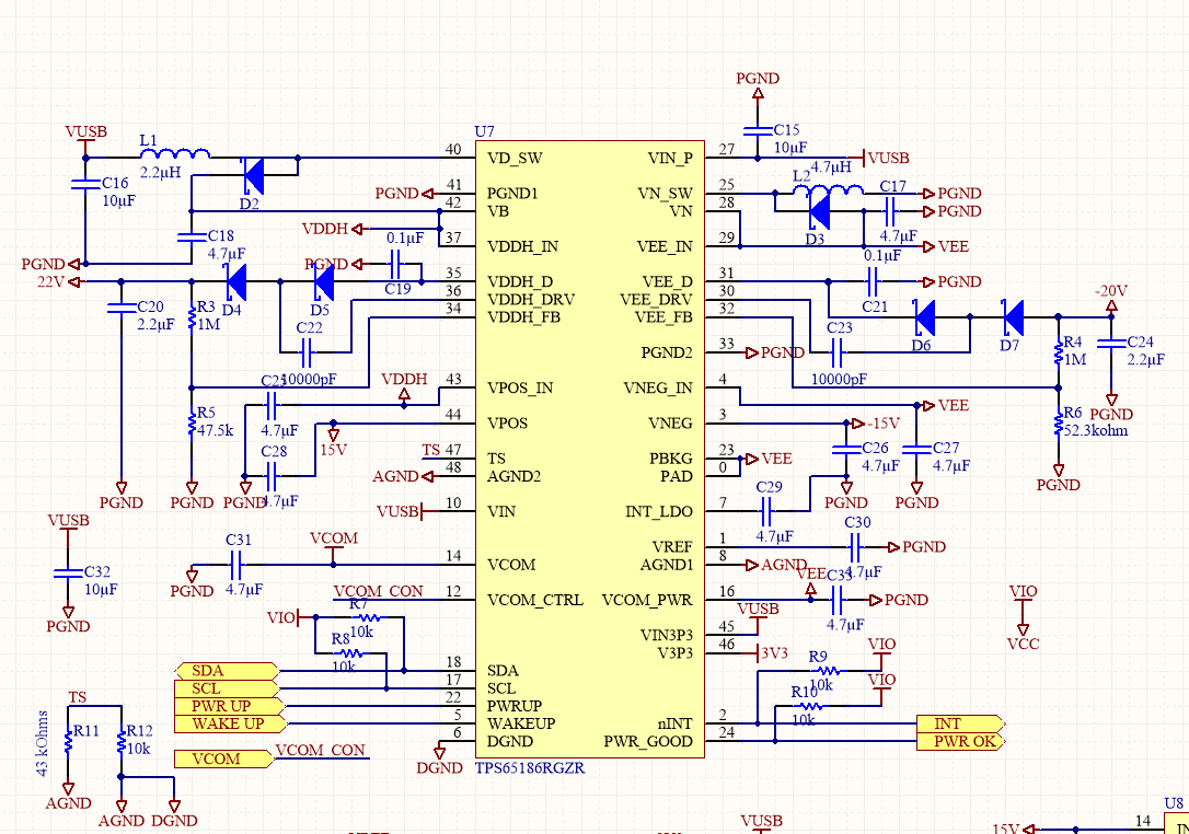
Hello, recently I have made the circuit for TPS65186, I followed most of the design guide given in documentation of EVM of TPS65185. So far all my circuit is good, except for it does not turn ON and I cannot find where the problem is. By the way I am not using IIC, I just want the power rails to be turned on. Please suggest some steps to start the debug.

  • Kiran,
    In the data sheet it says that you can power up if the WAKEUP pin and the PWRUP pins are pulled high. It will power up using the default power up sequence in the UPSEQx registers.

    8.4.4.1 SLEEP → ACTIVE
    WAKEUP pin is pulled high with PWRUP pin high. Rails come up in the order defined by the UPSEQx registers
    (OK to tie WAKEUP and PWRUP pin together).
  • Hello Gordon,

    I have pulled both POWER UP and WAKE UP pins high but there is no luck. Also to debug I connected a microcontroller and connect via IIC. IIC connection seems fine and i send start up command from the IIC but the power does not turn on. I am also attaching the circuit diagram that I made. Please suggest me some other method too.

    Even thought in schematic it says Vusb, I am only using 3.3 volts for the whole circuit.

  • In the mean time, I tried checking for the interrupt signals. I found that ULVO is always set, even though voltage in all pins are >=3.3V.
  • Kiran,
    It should be working. I am going to bring in the product specialist for this part. Maybe I am missing something.
  • Hi Kiran,

    Please measure VIN with an oscilloscope while toggling the PWRUP pin. It could be helpful to probe the nINT pin as well.

    If VIN is dropping due to the startup currents, you might need to add capacitance at the input, or raise the input voltage to reduce the current and give more room above the UVLO threshold.

    Best Regards,

    Rick S.

  • Hello Richard,

    Actually I have been debugging and I found out the same reason that you have told, so I changed my power supply. Then I was getting VN_UV after that. I solved that issue too but now I am getting VCOMF fault. When I probe VCOM i can see some high and low going pulse with+1.4 to -1.5v when DCDC tries to switch on.

  • Hi Kiran,

    This could be a layout issue, associated with the current path of that DCDC. This would include the path from the output cap to PGND and the GND of the input cap. I would recommend looking at the AGND layout, as the VREF capacitor is connected to PGND instead of AGND. Typically we recommend the VREF circuitry, AGND1, and AGND2 are isolated from any aggressors, including PGND return currents. An offset on the reference might affect other regulators such as the LDOs as well, so if you see similar pulses on other regulators it would indicate a reference layout issue.

    Best Regards,

    Rick S.