This thread has been locked.

If you have a related question, please click the "Ask a related question" button in the top right corner. The newly created question will be automatically linked to this question.

UCC28780: UCC28780EVM-021 behaviour before Brown-IN Voltage

Part Number: UCC28780

Hello,

I am using UCC28780EVM-021. When I connect it to power supply and start increasing the voltage from 0VAC, I am observing 3 different kind of PWM pulses upto Brown-IN voltage i.e. apprx. 75VAC.

1. 0VAC to 45VAC

2. 45VAC to 75VAC

3. above 75VAC

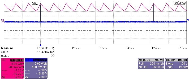
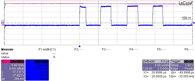
1. In the first range, I have the following waveform. When VDD equals VDDon, there is only one QL gate pulse (Blue in the waveform) of 2us duration (I have checked it by changing the time scale as well). The next pulse comes after apprx. 1.22sec. and this repeats upto 45VAC.

I want to know, which kind of fault is the chip sensing or what is the reason behind this kind of QL gate pulses in the range 0-45VAC? because I have made one circuit and in which the behaviour is not the same. In my circuit there are four QL gate pulses from the beginning up-to 30VAC. and then number pulse reduces to only one pulse.

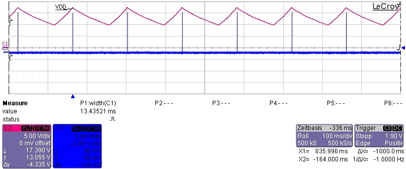
2. When Vin is greater than 45VAC and less than Brown-IN, the waveforms are as follows.

At every VDDon, there are 4 PWML pulses. I think this is the case when it is sensing that Brown-IN voltage is not reached. Because it behaves the same till Brown-IN voltage. And above the Brown-IN voltage, it works normal and we have constant VDD and QL gate pulses depending on load.

  • Hello Nisarg,

    The pre-start pulse patterns that you are seeing on the UCC28780EVM-021 are normal.

    In the case of 0-45Vac, with 1 pulse every ~1.22 seconds: the controller is reacting to the condition that appears to behave as CS short-to-GND wherein the CS signal has not reached 0.28 V within 2 us (see page 35 of the datasheet). The very low bulk voltage does not increase the primary current to reach the Vcst(sm1) threshold within the allowed 2-us time interval. This is interpreted as an apparent CS-short fault because the controller cannot distinguish between a lack of threshold crossing and a true short-to-GND. The time interval is short to avoid excessive peak current (undetectable) in the event of a true short-circuit.

    In the case of 45Vac – 75Vac, with 4 pulses every UVLO cycle: it is normal pre-Brown-in operation as you expect.

    In your other circuit, I am not sure why you are seeing 4 pulses below 30Vac. However, it may be possible if the CS signal has noise or a signal shape that does reach the 0.28V threshold during the first pulse, which gets the control state past the short-to-GND detection. Having achieved the 0.28-V threshold in the first cycle, it continues with the remaining 3 pulses, but can’t start because of the low pre-Brown-in voltage. Apparently, above 30Vac, the first-pulse CS signal waveshape changes enough that the 2-us time limit is exceeded and the control reverts to the expected 1-pulse behavior until AC input is again high enough for the primary current to hit the 0.28V threshold within 2 us. You can check the CS-input waveform with an oscilloscope to verify this conjecture.

    I hope this explains what you are seeing. Let me know if you have any other questions.

    Regards,
    Ulrich
  • Hello Ulrich,

    My problem " In my circuit there are four QL gate pulses from the beginning up-to 30VAC. and then number pulse reduces to only one pulse." is a bit solved. But now, I have somewhat same kind of behavior as demo board but the voltage range is different.

    For demo board it was:

    1. 0VAC to 45VAC

    2. 45VAC to 75VAC

    3. above 75VAC

    For my circuit

    1. 0VAC to 30VAC

    2. 30VAC to 50VAC

    3. above 50VAC I am having only 1 pulse of 200ns. I am not able to find which kind of fault it is from the datasheet section.

    In the datasheet, many fault conditions are explained when the circuit is normally working. But before brown-in voltage, if some fault case is sensed, then how the chip behaves, is not described.

    Does CS pin senses the ramp signal during leading edge blanking time or it starts sensing after this time? because I have a spike at the beginning of CS ramp i.e. when the MOSFET turns ON. Could you suggest some steps to reduce the amplitude of the spike or to completely eliminate it?

  • Hello Ulrich,

    Thank you for this detailed explanation.
  • Hello Nisarg,

    I, too, looked through the datasheet (DS) and could not find any fault corresponding to a single pulse shut-down while in the brown-in condition. I do not believe that there is an undocumented fault condition. Instead, I wonder if there are more pulses that you are not capturing. Try reducing the sweep rate to 10~20us/div on the oscilloscope to capture more pulses to the right of the first one.

    The CS input senses the current ramp signal after the leading-edge blanking (LEB) interval. For SET = 0V, this LEB time is 130ns. For SET = 5V, LEB is 200ns. For your circuit operating above 50Vac but under your Brown-in threshold setting, the 200-ns pulse width indicates that the CS voltage is >0.8V at the end of the LEB time. This can happen when the leading-edge spike has not subsided below 0.8V before the LEB time expires.

    The turn-on spike of current is normal and basically unavoidable. The spike occurs because the lower MOSFET turn-on discharges the switched node capacitance. The MOSFET’s own Coss is discharged within the MOSFET channel, and is not seen by the sense resistor. However, the capacitances of the upper MOSFET, the transformer windings, and the output rectifier (reflected through the xfmr) are also discharged and this current IS seen by the sense resistor. The peak magnitude of this current spike depends on the falling dv/dt of the MOSFET when turning on.

    There are trade-offs to consider when dealing with this spike. The total charge to be discharged is highest at high line. This charge is the same whether the spike amplitude is high or low, so a low peak current will take longer to discharge than a high-peak current. To contain the spike within the LEB time, it would require a high peak amplitude, but that requires high dv/dt of the MOSFET Vds which might subsequently cause an EMI problem. One can try to minimize the collective switched node capacitance by choosing components with lower Coss, and fewer turns on the primary winding, however, there is a practical limit to this idea.

    The final alternative is to add a spike filter on the CS input. Normally there is a resistance (denoted by Ropp) in series with the CS pin and the current sense resistor which is used to adjust the Over Power Protection (OPP) curve as a function of input voltage. Because Ropp is normally there, a small capacitance placed on the CS input will form an RC filter on the current sense signal. This filter can be tuned to attenuate the turn-on current spike seen at CS to avoid triggering the shutdown after LEB expires.

    The benefit of the RC filter comes at a price: the R-C time constant adds a delay to the current sense and allows a higher current ramp peak than expected unless the delay is accounted for. The design equations do allow for an estimated RC delay to be taken into account when calculating the sense resistance. So instead of reducing or eliminating the turn-on spike (which is very difficult, at best, to accomplish) the simplest course of action is to mask it with an RC filter on CS and account for the delay.

    In your situation, I suggest to simply double or triple the capacitance and see if the 200-ns shutdown problem goes away. Worry about the extra time delay later. Test your start-up over the full low-to-high line range to be sure it works at all input conditions. If so, then begin to reduce the capacitance value on CS until it just begins to exhibit the 200-ns shutdown again. This indicates your minimum capacitance without margin. Add back some capacitance (maybe +30~50%, or more if necessary) to regain design margin and note the time constant. Recalculate the sense resistance and Ropp (using the Mathcad or Excel tools, or DS equations) based on this time constant to re-establish the desired output power limit.

    Please let me know if this resolves your issue or if you have any questions with this.

    Regards,
    Ulrich