This thread has been locked.

If you have a related question, please click the "Ask a related question" button in the top right corner. The newly created question will be automatically linked to this question.

TPS65381A-Q1: Unable to leave STANDBY state by setting CANWU_L = 1

Part Number: TPS65381A-Q1
Other Parts Discussed in Thread: TCAN1043HG-Q1,

Hello everyone,

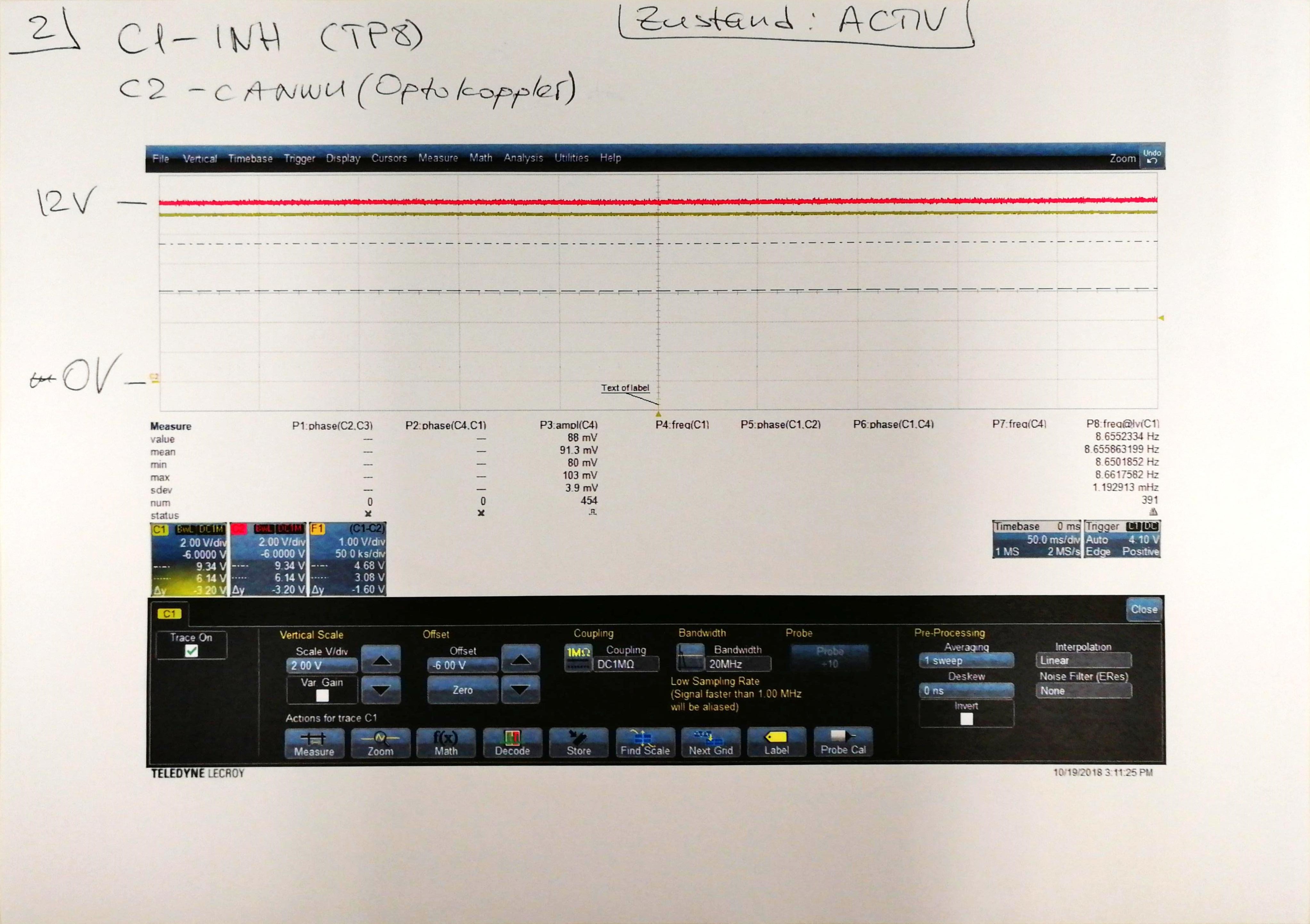
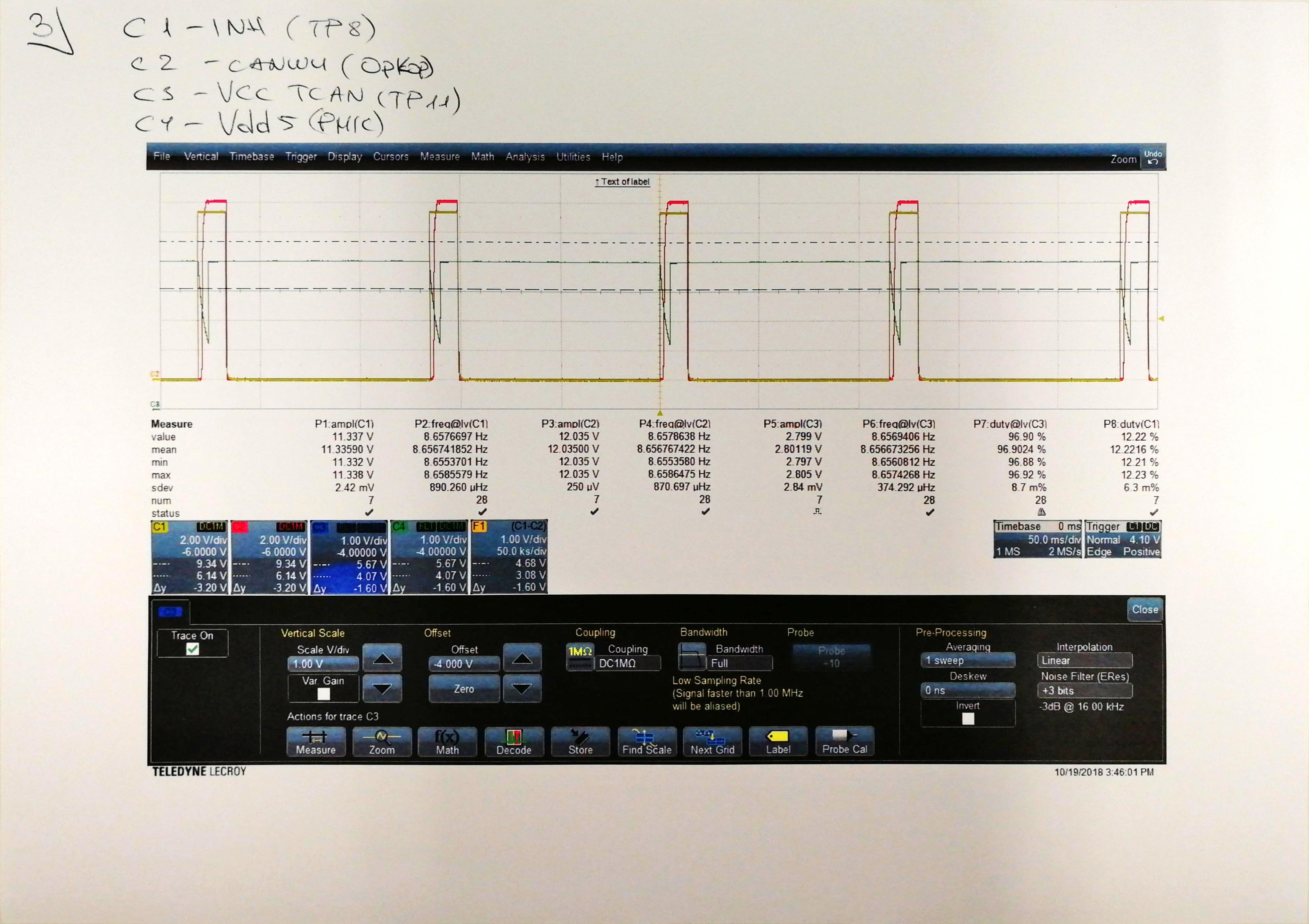
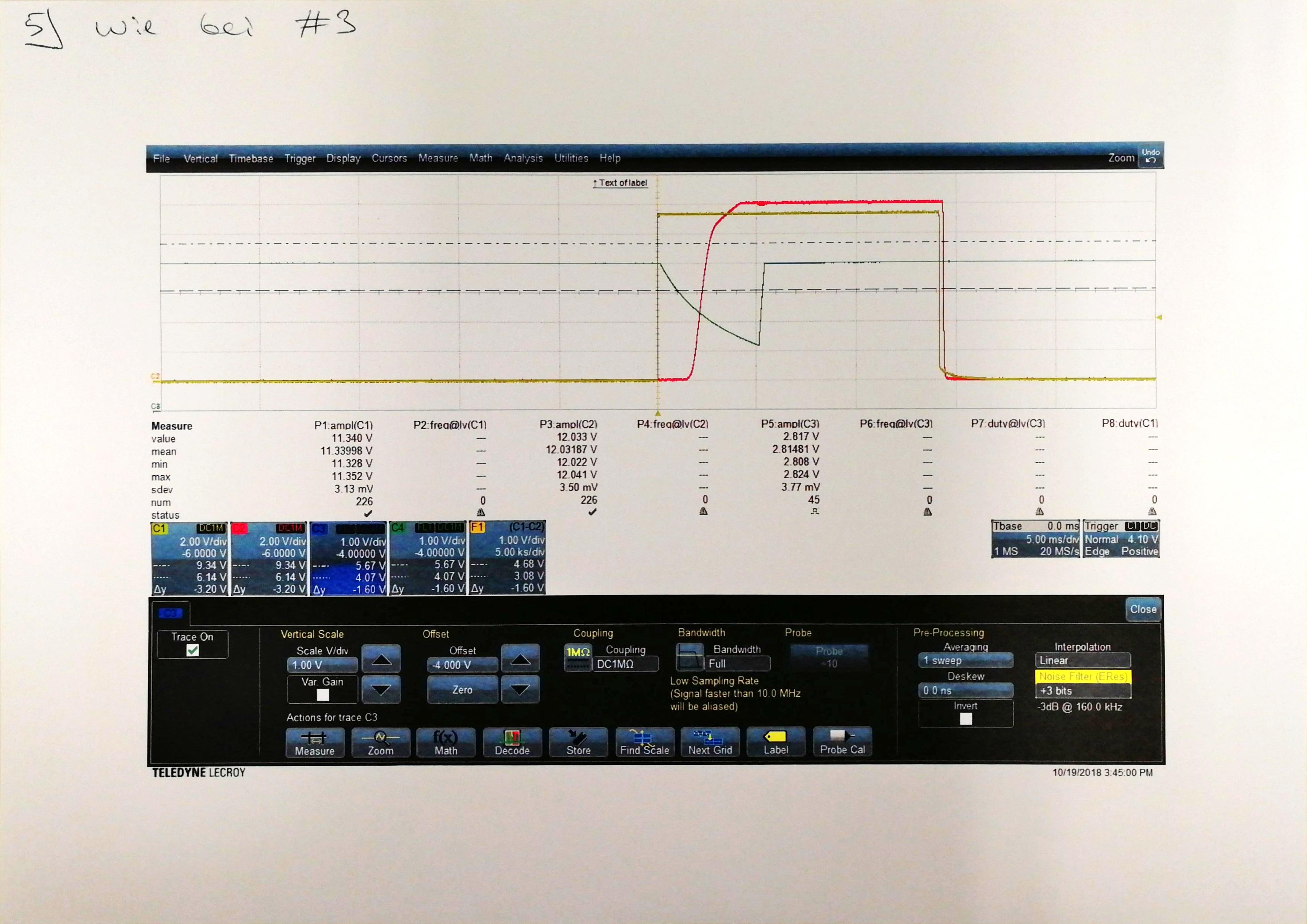
I am currently using the TI product TPS65381EVM with TPS65381A-Q1 PMIC and evaluation modul TCAN1043HG-Q1. Vsup of TCAN is connected with an external voltage source = 12 V and Vcc of TCAN  is connected with VDD3/5 = 5 V on PMIC.

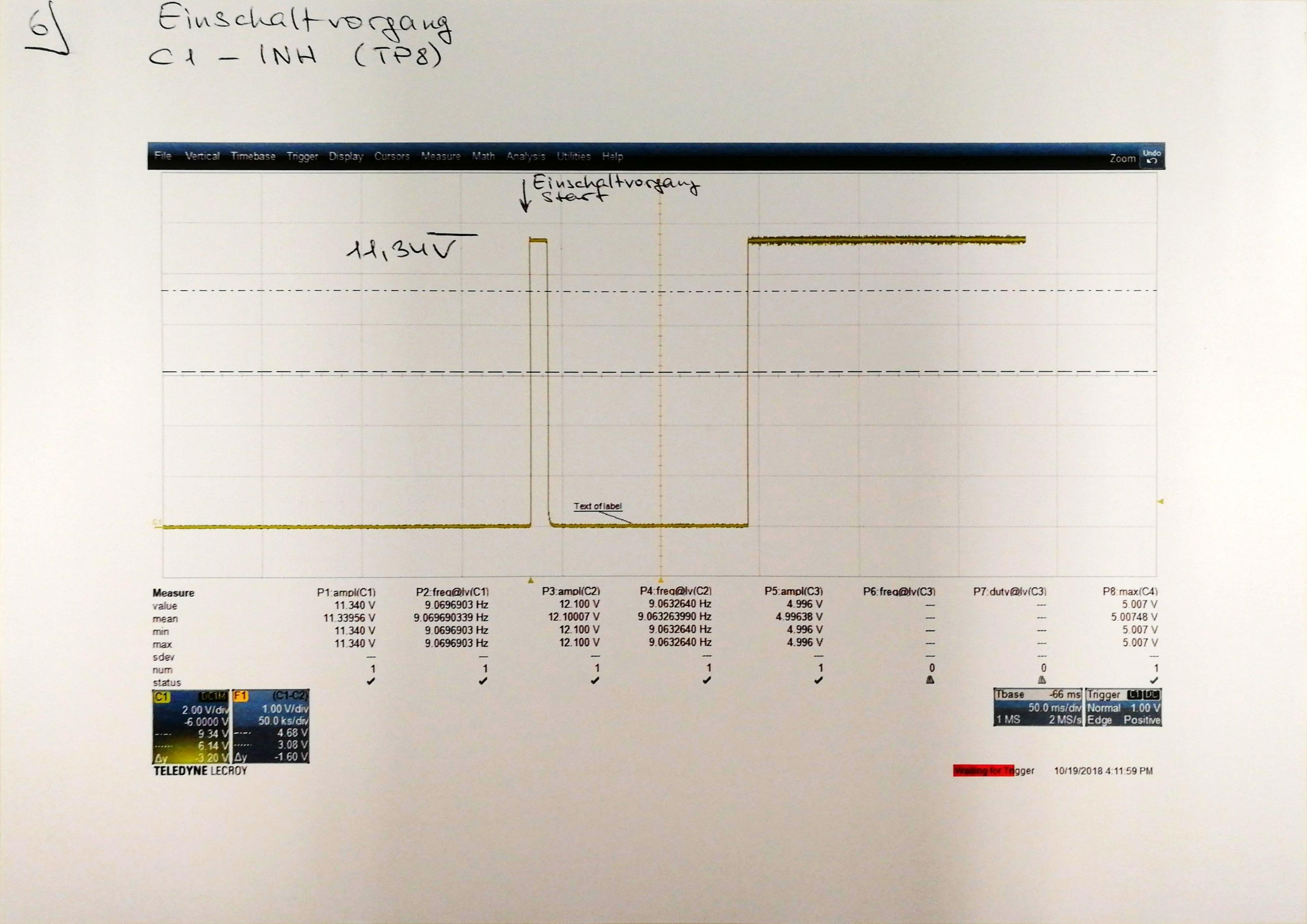
My purpose is to leave STANDBY state by changing CANWU_L bit to 1. As I suspect, I can change CANWU_L bit connecting INH pin on TCAN with CANWU_C pin on PMIC. So when PMIC is in STANDBY, TCAN gets no voltage from PMIC and goes also in Sleep Mode (INH is floating). If I send any CAN message to TCAN, wake up event occurs and INH pin will be set HIGH = gets 12 V. At this moment I've expected PMIC goes to RESET, DIAGNOSTIC and then ACTIVE state, but it stays in STANDBY. IGN pin is not connected.

What am I doing wrong? Thanks for your attention.

  • Hi Ivan,


    Have you also provided power (12V) from the same supply that is powering the TCAN to the VBATP (power supply input) and VBAT_SAFING (voltage monitoring supply input) pins for the PMIC? There is a jumper at the top of the EVM, J1, that will bridge the VBATP and VBAT_SAFING nets so only 1 power connection to the TPS65381A-Q1 EVM is needed. Once the supply is connect to the PMIC, when the CANWU pin or IGN pin of the device go high the device will power up. If either of these pins is not supplied the device will remain in STANDBY state. So in your use case the INH output from the TCAN should connect to the CANWU pin (CANWU_C on EVM connector or to TP9).


    One note about the state machine: unless you have MCU in the system that will properly configure the TPS65381A-Q1 when it powers up and is in DIAGNOSTIC state the TPS65381A-Q1 will have a DIAGNOSTIC state timeout after ~ 512ms in DIAGNOSTIC state and it will transition to SAFE state. Normally the MCU boots and runs system diagnostics and configures the PMIC, while the PMIC is in DIAGNOSTIC state, then the MCU transitions the PMIC to ACTIVE state (or for software debug) can keep the MCU in DIAGNOSTIC state.


    Please let us know if you have any more questions.

  • Hi Scott,

    thanks for your reply. This issue is not solved yet and I have still no idea what could be a possible reason. I wrote more accurate description of it below.

    Scott Monroe said:
    Have you also provided power (12V) from the same supply that is powering the TCAN to the VBATP (power supply input) and VBAT_SAFING (voltage monitoring supply input) pins for the PMIC?

    Yes, I use only one power supply (12 V) for PMIC and TCAN.

    TCAN has V_sup, V_cc and V_io. V_sup is directly connected with 12 V. V_cc gets 5 V from PMIC (CON1, VDD3/5). V_io is connected with V_cc through the JMP6. 

    Scott Monroe said:
    There is a jumper at the top of the EVM, J1, that will bridge the VBATP and VBAT_SAFING nets so only 1 power connection to the TPS65381A-Q1 EVM is needed.

    J1 is set and PMIC has only 1 power connection.

    Scott Monroe said:
    One note about the state machine: unless you have MCU in the system that will properly configure the TPS65381A-Q1 when it powers up and is in DIAGNOSTIC state the TPS65381A-Q1 will have a DIAGNOSTIC state timeout after ~ 512ms in DIAGNOSTIC state and it will transition to SAFE state.

    MCU is already integrated and can detect and control PMIC states.

    Scott Monroe said:
    when the CANWU pin or IGN pin of the device go high the device will power up. If either of these pins is not supplied the device will remain in STANDBY state.

    Here I have a problem. Wake up through IGN pin works fine but PMIC can't leave STANDBY by setting CANWU pin high (all outputs on CON1 stay low).

    After PMIC transition to STANDBY, TCAN goes in sleep mode as well (V_cc under-voltage event). INH pin goes low. So at this point I can send a random CAN message to TCAN to cause a wake up event, that sets automatically INH pin high. Therefore CANWU pin goes high, the PMIC must be powered up but it doesn't work. It stays in STANDBY till the IGN pin will be set high.

    I've also tried to power CANWU pin from external power supply to simulate wake up event but it didn't help as well. 

    What could be a possible reason?

    Thanks for your attention.

    Regards,

    Ivan

  • Hi Ivan,

    I have just used my EVM with CANWU and it works fine. Which CANWU_C connection are you using, CON1 or CON3? The easiest is the outer bottom pin on CON1 as the CANWU_C, then use a multi-meter and monitor TP9 to make sure the CANWU signal is actually getting to the TPS65381A-Q1 CANWU pin. Also, make sure R10 series resistance is still populated on your EVM, if that was removed there will be no connection path to the device CANWU pin.

    Best Regards,
    Scott
  • Hi Scott,

    thanks for your help. I think it could be a subsequent error because I found one more problem right now. I'll check the entire circuit for any other failures and then inform here.

    Regards,
    Ivan
  • Hi Ivan, Since I haven't seen any follow up for a couple of weeks I'm assuming you have found the other issue and resolved it. If not please let me know if you still need further help.
  • Hi Scott,

    I'm facing a new problem with INH - CANWU_L connection. I've made a couple of oscilloscope measurements to look at INH pin behavior during ACTIVE - SAFE - STANDBY transition. To avoid any leakage I've build in an optocoupler between INH and CANWU_L.

    Here follows description to my oscilloscope measurements:

    1. (Expected) State: STANDBY, channel 1 (yellow) is INH pin on TCAN, channel 2 (purple) is CANWU_L pin on optocoupler. In this case I expected LOW signal but as we see it comes constantly logical 1 for a while with 8,65 Hz frequency.

    2. State: ACTIVE, same channels as on the first one. Voltage of INH pin is lower than 12 V (11,34 V). On the 6th image you can see it more precise.

    3. (Expected) State: STANDBY, channel 3 (blue) is Vcc on TCAN (TP11), channel 4 (green) is Vdd on PMIC.

    4. (Expected) State: STANDBY, only channel 4 is EN pin on TCAN (TP5).

    5. How by the 3rd image but only single event and more precise.

    6. INH pin by power-on process.

    Do you have any idea about this strange INH pin behaviour? 

    Regards,

    Ivan

  • Hi Ivan,

    This question about the INH output is really best suited to the forum for the CAN transceivers, but since I used to work on them I'll answer at the high level.  When both the PMIC is in its low power STANDBY mode and the CAN transceiver is in its low power mode called sleep, the only power being used in the system is normally the battery supply to the PMIC VBATx pins and the VSUP pin of the CAN transceiver.  The CAN Transceiver is monitoring the CAN bus and it's WAKE pin for it's wake up events.  The PMIC is monitoring the IGN and CANWU pin for it's wake up events. 

    The INH output of the CAN transceiver should not be dependent on the PMIC.  The INH will go high via a pull up transistor to the VBAT supply to the CAN transceiver when an appropriate CAN frame meeting the wake up pattern, WUP, is detected on the CAN bus or the WAKE pin on the CAN transceiver goes high.  Once this happens INH is pulled up to the battery supply and that voltage is output to INH pin, which normally is connected to CANWU on the PMIC.  Once the PMIC detects high on CANWU pin it will power up through RESET state to DIAGNOSTIC state.  It is assumed in DIAGNOSTIC state the MCU will be powered up and part of the boot procedure will be running diagnostics on the system, configuring the PMIC and enabling the CAN transceiver via the nSTB and EN pins. 

    The plots imply the optocoupler or CAN transceiver is putting a large transient load onto what I assume is the VDD5 rail on the PMIC which seems to already be powered and causing it to have a large undervoltage dip.  This seems to indicate you are not using the CAN transceiver with the PMIC as expected or assume from TI.  This CAN transceiver has a UV detection and lock out so I assume it is detecting the UV on the supply line via for it's VCC and IO's and going to it's standby state due to this detection.  If you look into section 10.3.7.6 Undervoltage Lockout (UVLO) of the TCAN datasheet you will see one of these UV's will cause the device to protect the bus and make INH high Z. So it seems this happens, INH goes high Z the CAN bus or local WAKE pin to the CAN XCVR is still active and re-wakes the device up and INH will go high again, likely with some timeout protection time which makes it look like a periodic wake signal on INH. 

    The PMIC should latch the first high on CANWU (into flag bit CANWU_L) and remain on until the WR_CAN_STBY command (or other power down event) occurs.

    Hopefully that can help track down your issues.  If you have more detailed questions on the TCAN please post to their forum using the part number in a separate E2E thread.

  • Hi Scott,

    thanks for the advice! I appreciate the effort. We'll check out your solution next week.

    Regards

    Ivan

  • Hi Ivan,

    It has been 12 days since my last answer so I'm assuming you have worked through the other issues and didn't have a further issue. I'm going to close this thread for now. If you have further questions please re-open it or start a new thread if it is on a different topic.