This thread has been locked.

If you have a related question, please click the "Ask a related question" button in the top right corner. The newly created question will be automatically linked to this question.

LM2755: Dimming Question

Part Number: LM2755

Hi,

My customer has the following questions...

A few details on the setup first:
• Iset to 15mA with a 16.6k resistor.
• The current is being measured through a single red LED.
• A 50ohm series resistor is placed in the path of the LED, and a differential voltage is captured across the resistor for the current measurement.

1. When the highest current step is chosen and dimming is disabled the measured waveform is constant dc current. In the capture below the waveform is as expected.


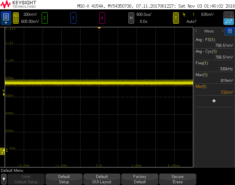
Register Dump: {'high_time': '0x80', 'low_time': '0x0', 'enabled': True, 'high_level': '0xff', 'step_size': '0x80', 'dimming_enabled': False, 'delay_time': '0x0', 'fall_time': '0x0', 'low_level': '0xe0', 'rise_time': '0x0'}
 
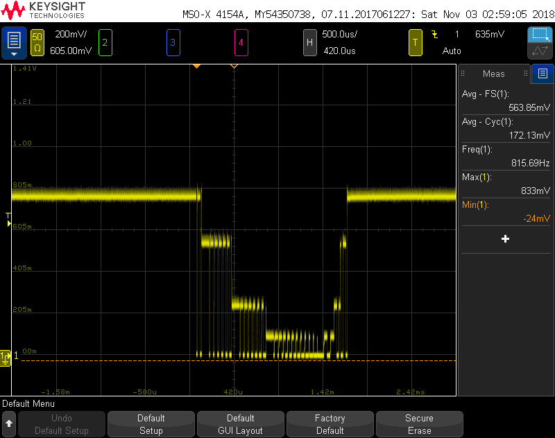
Now, when we drop the current step one level I am expecting to see a constant dc current with a smaller magnitude. However the resulting waveform has a PWM element. Why is the current not constant?


Register Dump: {'high_time': '0x80', 'low_time': '0x0', 'enabled': True, 'high_level': '0xfe', 'step_size': '0x80', 'dimming_enabled': False, 'delay_time': '0x0', 'fall_time': '0x0', 'low_level': '0xe0', 'rise_time': '0x0'}


2. The next question I have involves the dimming functionality of the LED driver. In the data sheet the dimming waveform is specified as a step function with constant current steps.

When dimming is enabled we see a PWM element to the entire waveform. Is this an expected result?
 
Register dump: {'high_time': '0x80', 'low_time': '0x0', 'enabled': True, 'high_level': '0xfe', 'step_size': '0x80', 'dimming_enabled': True, 'delay_time': '0x0', 'fall_time': '0x1', 'low_level': '0xe0', 'rise_time': '0x1'}

 
{'high_time': '0x80', 'low_time': '0x0', 'enabled': True, 'high_level': '0xff', 'step_size': '0x80', 'dimming_enabled': True, 'delay_time': '0x0', 'fall_time': '0x1', 'low_level': '0xe0', 'rise_time': '0x0'}

Here is another dimming waveform, this time with constant current. You can see that only the dimming waveform has PWM.

3. Lastly with dimming enabled and high_level equal to low_level we see the dimming waveform add a current spike.

 
{'high_time': '0x64', 'low_time': '0x1c', 'enabled': True, 'high_level': '0xee', 'step_size': '0x80', 'dimming_enabled': True, 'delay_time': '0x0', 'fall_time': '0x0', 'low_level': '0xee', 'rise_time': '0x0'}

This spike on the dimming waveform adds to the overall brightness of the LED. When we set the current low and use the dimming function we are actually seeing more current than we expect. Why does the dimming waveform behave like this?

Thanks,

Chuchen

  • Hi Chuchen,

    Thanks for your question, This device is a very old device. What your application?
    For the question 1, please make sure the 'dimming_anabled" should be set with disable. It should be DC current with disabled setting;
    For the question 2, what code you send to device when you have enabled the dimming function? the waveform seems ok;
    for the question 3, if you want to set high_level =low_level, you can try to set high_level to the value of low_level, don't set the low_level to a high value. I'm not sure what cause those spike, I guess because you set the low_level to a high value, there is a high quantity energy.

    Sean
  • Hi Sean,

    Let's focus on question 1.

    Both of the waveforms shown in question 1 have dimming disabled for the diode we are using D1. (register 0x10 = 0xB1)

    The only thing that is changing from the first waveform to the second is the high_level register 0xA9. (waveform 1: 0xA9 = 0xFF, waveform 2: 0xA9 = 0xFE)

    Given that dimming is disabled and the only register change is to the high_level why is the second waveform not DC?

    Thanks,

    Justin

  • Hi Justin,

        I don't have much ideal about this phenomenon, but I have some guess. Because reg 0xA9 0xA2 was used to control the waveform when you disable the dimming waveform on output D1, you may can't change those regs and you need to write high_level=0xFF, if you write high_level less than 0xFF, it will enable the dimming waveform automatically. Because when the dimming waveform is disabled, The current is set by Rset.

       So you can compare the waveform when you enable the dimming waveform with the waveform you get now. Looking forward your response.Thanks.

    Sean

  • Hi Sean,

    The first three images attached show the waveform with dimming enable, dimming disabled. What register settings should be used to get a constant current?

    Thanks,
    Justin

  • Hi Justin,
    You can try just enable the D1/D2/D3 output with reg 0x10(bit0-2) and disable the bit3-5. I think the constant current was determained by the resistor connected to "ISET" pin. I don't think you can change the regs with dimming mode to get the constant current? BTW, what the application? is your customer need constant current during the dimming mode? if yes, maybe they need analog diming, not pwm dimming?
    Regards
    Sean