This thread has been locked.

If you have a related question, please click the "Ask a related question" button in the top right corner. The newly created question will be automatically linked to this question.

LM3405: On by default, getting hot; suggestions

Part Number: LM3405

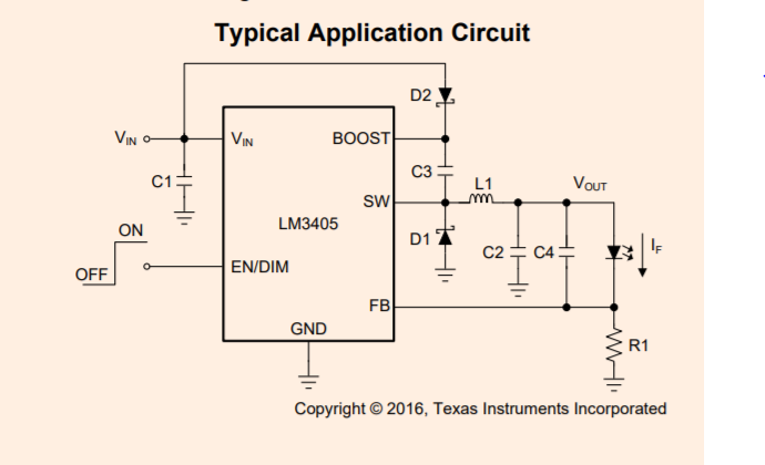
Hi. I'm using the LM3405 in the configuration as displayed on the first page of the datasheet (first image below)). 

Vin = 12V, and I have only 1 LED with Vf = 3.5V @ 1A. 

A few things that I noticed: 

1. With the LED disconnected, EN pin low I get Vsw = 5.3V

2. With the LED connected, EN pin low, I get Vsw = 5.7V, Vfb = 20mV and the LED is on (We need LED to be off, of course under this condition)

3. With the LED connected, EN pin toggling @50% duty cycle, freq = 2.5kHz, the Part gets hot (very hot). the higher the duty cycle the hotter it gets. 

I just found out after more careful reading of the datasheet that I need to maintain a max voltage drop of 5.5V across Boost and SW pin, which due to my high Vin, I'm violating. Is this violation the source of all my problems? If so, does the part allow such a high Vin assuming a larger number of series LEDs? 

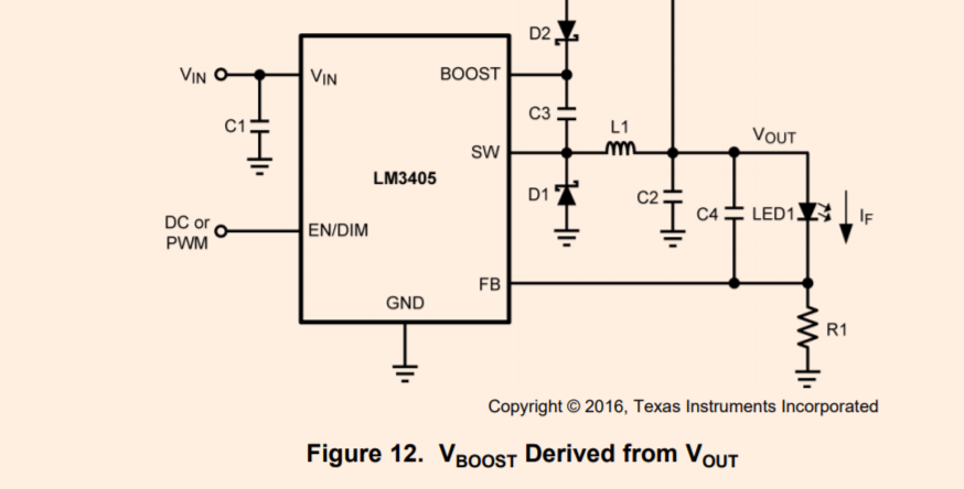
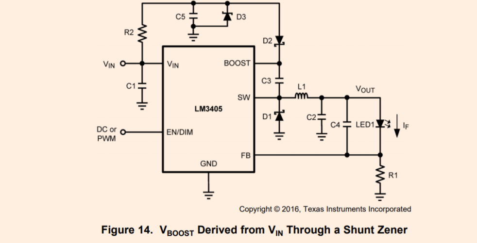
Secondly, what circuit topology should I use for my setup? Page 9 of the datasheet shows 4 options, and I think that both option 2 and 3 could work for me. But which one is better? I think last option has a higher power dissipation due to resistor and zener. So, where would this option be superior to the one in the middle picture. 

Thank you. 

Alin

  • That could be causing you grief. Option 3 limits the voltage on the BOOST pin, which would allow you to mitigate that violation. Just use zener with a voltage of less than 5.5V (e.g. 4.7V). Then the Vboost will always be within 4.7V of Vsw.

    The other, obvious question is, are your components rated for the current that you are drawing?
  • I prefer option 2 due to lower component count and power dissipation. Is there a downside to using option 2? 

  • Using option 2 charges the bootstrap capacitor to Vout and then Vboost gets bumped up as Vsw turns on. In this case Vsw and Vboost will always beseparated by a difference of Vout. I suggest option 3 because you control the voltage differential between those two pins.
  • Hello Alin,

    1)  There is switch leakage current or 0.1 uA per the datasheet.

    2)  What do you mean by on?  I would fix the boost problem since the IC can be damaged by sending 12V to the boost before looking at this more.

    3)  Again, I would fix the boost problem first before looking further into your design

    You definitely need to generate the boost voltage from something other than Vin.  The resistor zener option will give the most stable boost voltage.  If generated from Vout it will be lower, meaning less efficiency, and won't be available when the LED has been off.  The size of the resistor will depend on how much switching loss there is.

    Best Regards,