This thread has been locked.

If you have a related question, please click the "Ask a related question" button in the top right corner. The newly created question will be automatically linked to this question.

LM25005: EMC Problems

Part Number: LM25005

A while back I posted a thread about EMC problems with a LM25005 design. (https://e2e.ti.com/support/power-management/f/196/t/737098I believed the issue was solved but it turned out we still had emissions above the allowed thresholds.

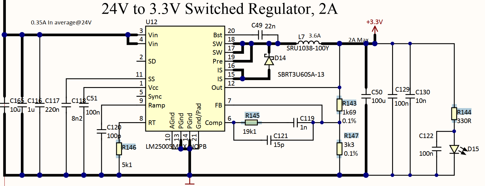
I'll try again to upload the schematics, layout and spectrum graph.

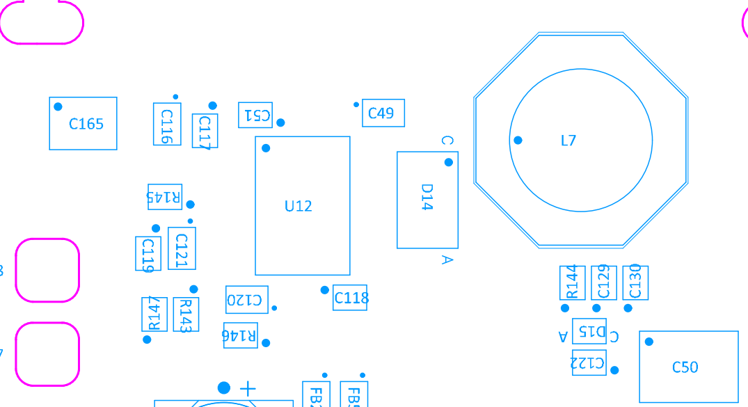
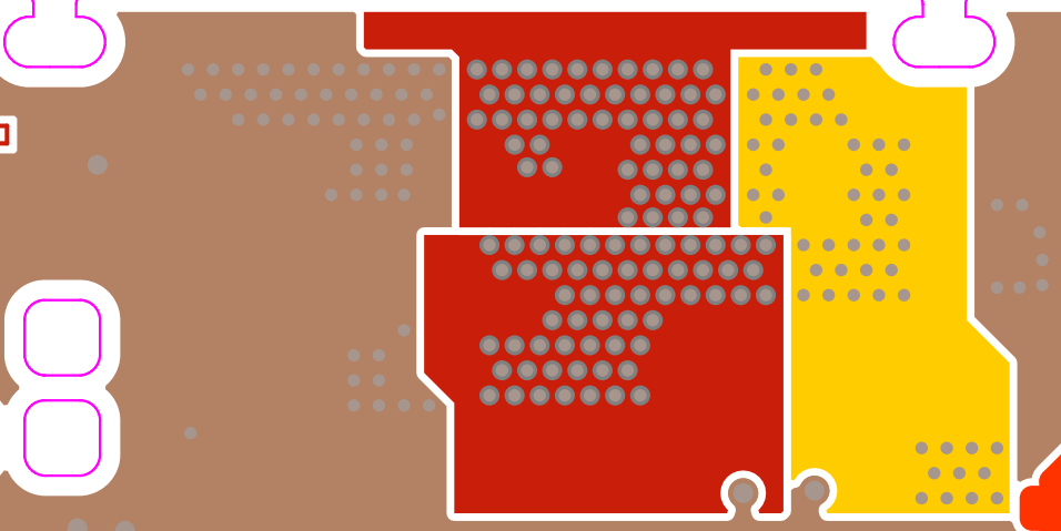
Layers, top to bottom:

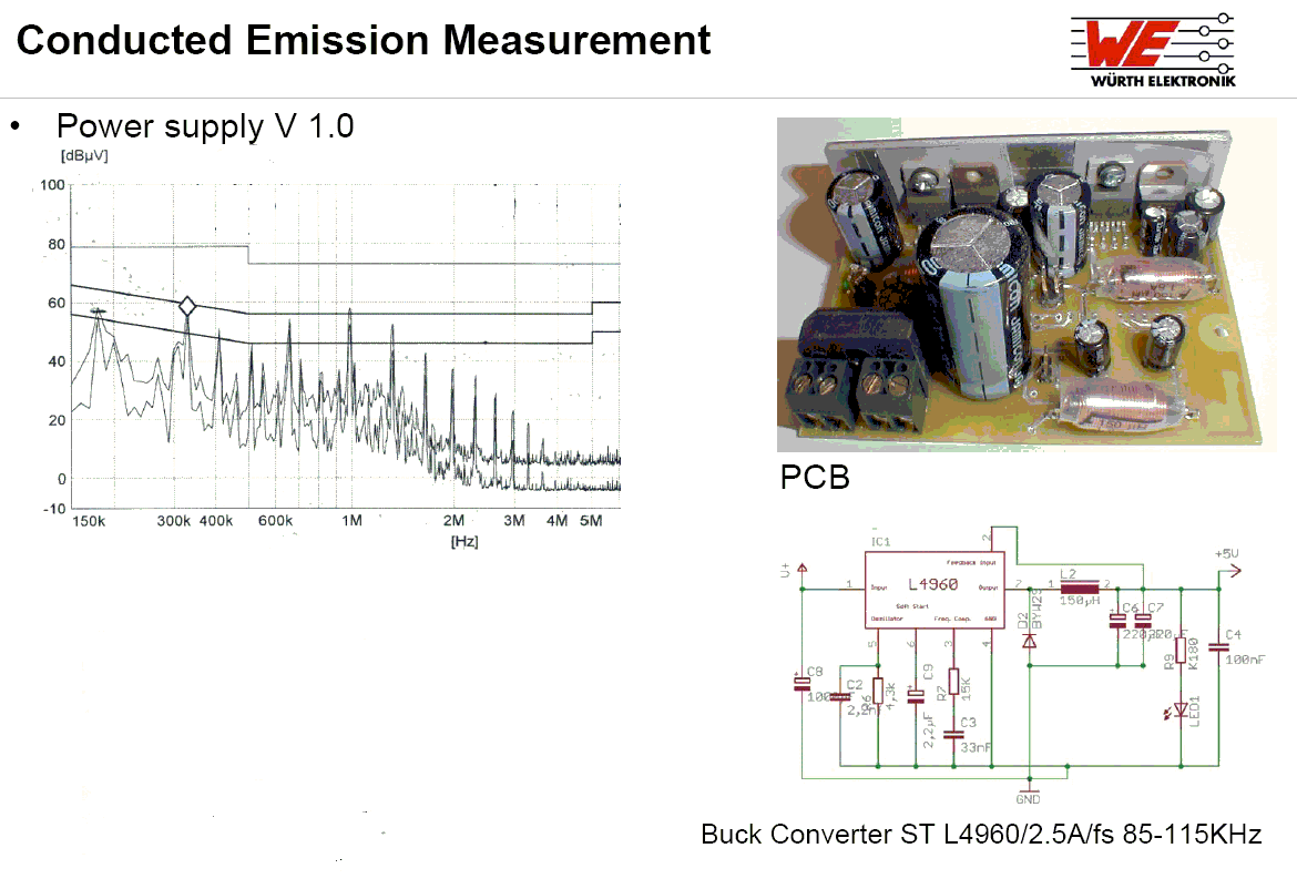
And the emission plot at first EMC-test:

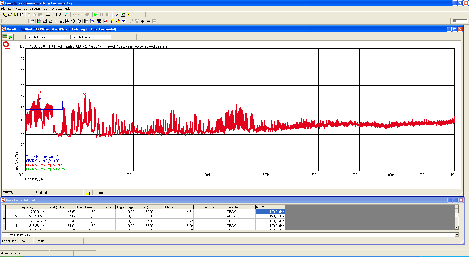
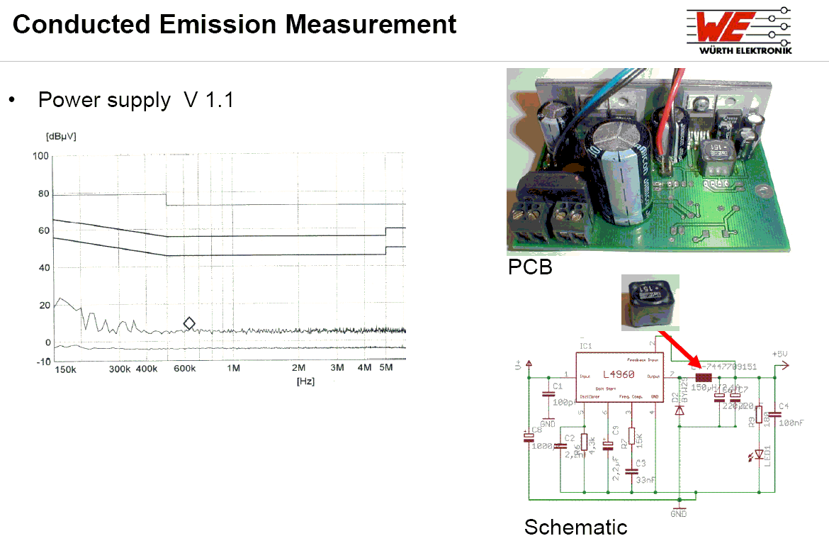
Changing the diode to B370-13-F moved the noise down in frequency, but it is still too much.

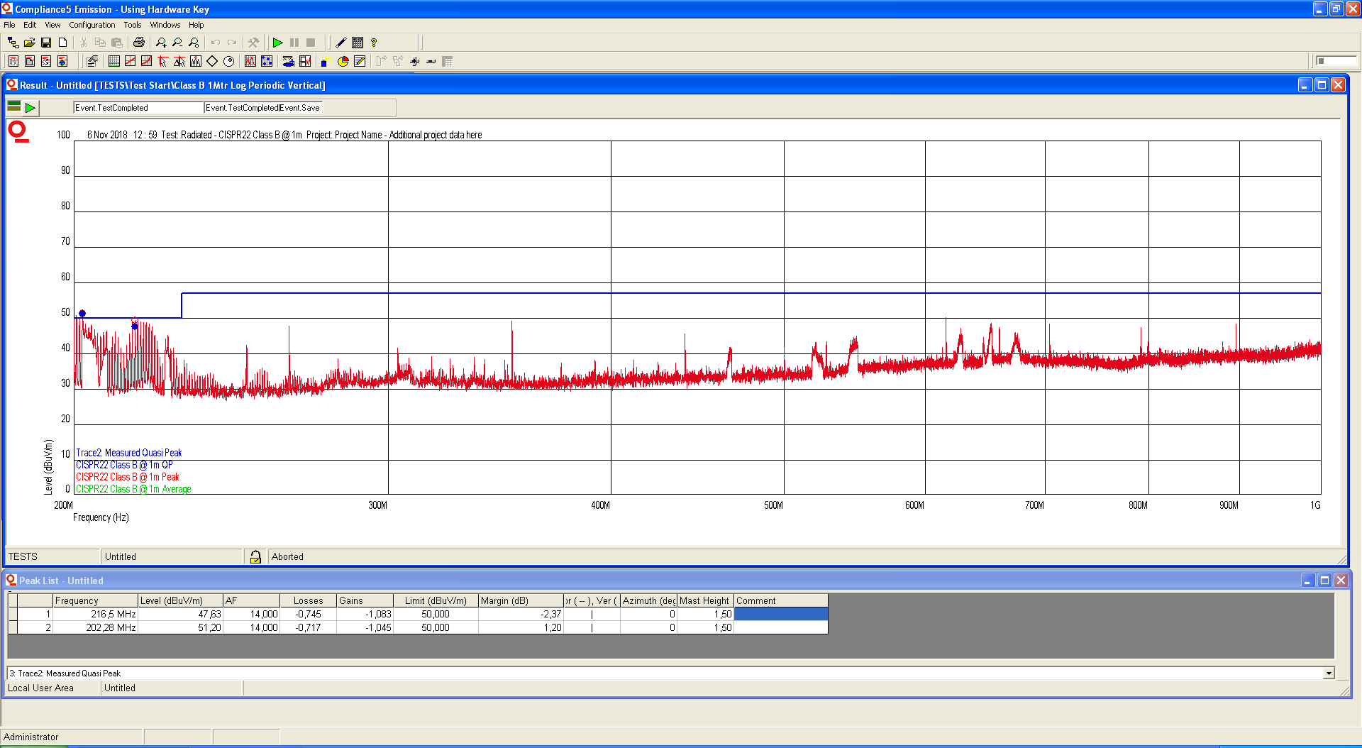
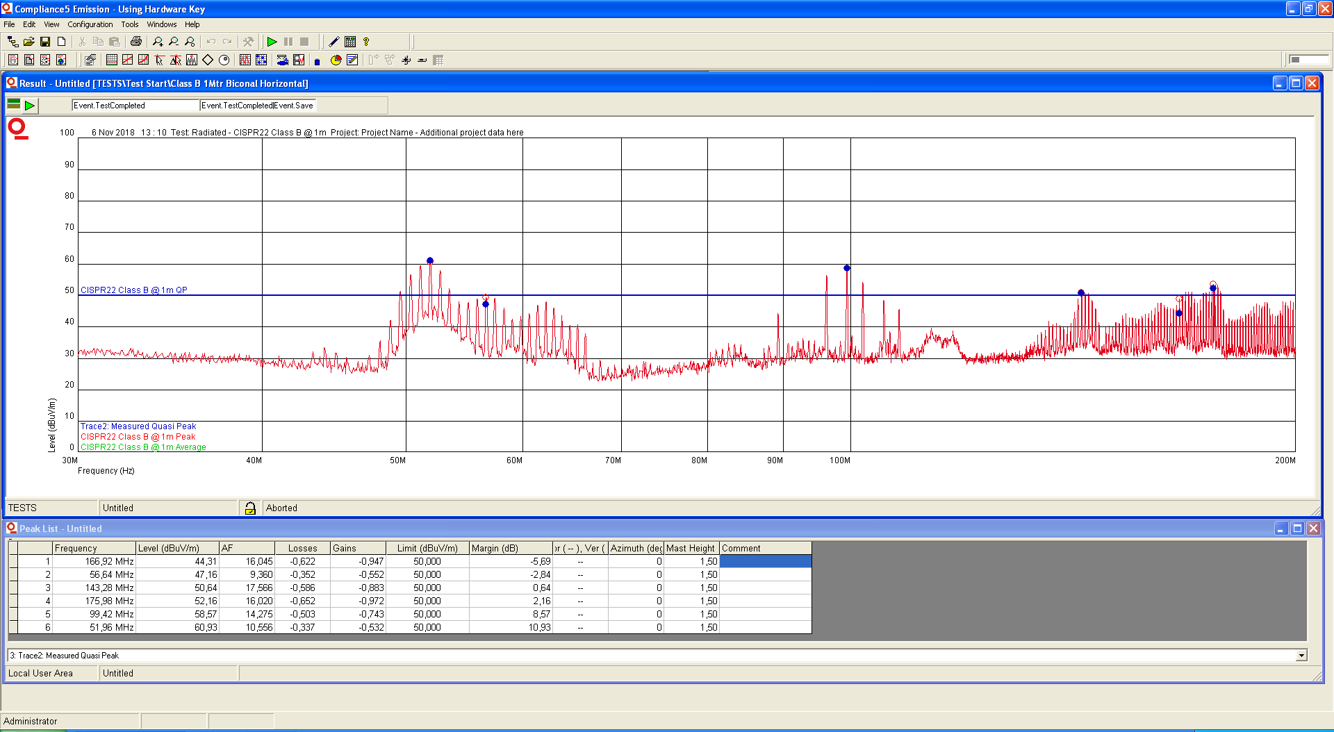
In addition to changing the diode I also added a snubber network as per the datasheet. That helped, but still not enough. I even put a small resistance in series with the boost capacitor to slow down the transitions. The difference was measurable but not great.

We have identified a few areas in the layout that could improve, such as:
-Better separation between planes to decrease capacitance
-Bteeter routing of the feedback signals.
-Better mounting of the diode and snubber. Since they where retrofitted they are squeezed in as well as they could be.

I'm very thankful for any input!

Best regards,

Andreas Wileur

  • Hi Andreas,

    One recommendation is to reduce the SW node copper area as this acts as a radiating antenna based on its high dv/dt. Also, you may consider placing a small decoupling cap from VIN to GND close to the VIN pin similar to where C51 is currently located. Finally, consider using a shielded inductor. For more information, please review this article series: www.how2power.com/.../EMI_Guide.php

    Regards,
    Tim
  • Hi Andreas,

    Are you using an input pi filter as well?

    Please see my layout recommendations:

    1. As Tim mentioned, I would recommend using a shielded inductor.
    2. I would also recommend using a small decuopling capacitor as close as possible to VIN/GND of the device. You will want to minimize this parastic loop.
    3. If there is switch node ringing, you can also experiment with a boot resistor to slow down the switch node's rising edge.
    4. It is critical to shrink the switch node area/traces as much as possible. You can also eliminated all the vias on the switch node.
    5. Another option is to have the majority of the input/output plane on a mid layer, and have the majority of the top layer be ground. This will also act as shielding to your signals.
    6. You could try adding a high frequency bypass capacitor at the output as well.

    Best Regards,
    Katelyn
  • Hi Andreas,

    why have you set such a high switching frequency? 800kHz will cause lots of EMC trouble!! I would set the switching frequency to 300kHz.

    And I don't see any input filter. Even only a simple high current ferrite bead of 1µH (low frequency inductance) can provide a dramatical improve. A proper pi-filter at input, as Katelyn already recommended, can do even much more...

    Kai

  • Thank you for all input!

    I do have an input filter, but it is shared with another regulator. I guess adding one spcecific to the LM25005 is a good idea.

    800kHz was choosen because webbench set the values, but I'll definitely try a lower frequency. It was on my list but somehow got lost.

    Again, thank you very much. I'll report back later.

    Best regards,

    Andreas Wileur

  • Hi Andreas,

    I wouldn't share the input filter with another regulator. Especially not when the switcher is producing so much EMI. Treat the input filter as part of the switcher, but not as a nice-to-have which can be shared with other circuitry. So, the input filter must sit very close to C165. In this frequency range every millimeter counts. This will also minimize unwanted crosscoupling between the regulators.

    Kai
  • Hi Andreas again,

    I like to take this ferrite bead for the filtering in most of my circuits. Keep in mind that at very high frequencies only ferrite beads can provide useful filtering impedance.

    The advantage of this type of ferrite bead (real wire covered by ferrite material) is that the ferrite bead can handle some DC current (bias) without going into magnetic saturation:

    2743021447.pdf

    Maybe you can even find a better one.

    Another issue is the switching inductor. When using an unshielded inductor this can happen:

    When using a magnetic shielded inductor, on the other hand, the EMI can be extremely reduced:

    But you have a magnetic shielded inductor, right?

    Kai

  • Thanks, I do, I even checked the double checked datasheet to be sure because the part has tiny holes in it.
  • Hi Andreas,

    I want to follow up on your EMI testing. Do you have any additional questions regarding the feedback from Tim or myself?

    Best Regards,
    Katelyn
  • Hi Andreas,

    If there are no additional questions, I am going to close out this thread.

    If you have any additional questions, please respond and this thread will reopen.

    Thank you,
    Katelyn