This thread has been locked.

If you have a related question, please click the "Ask a related question" button in the top right corner. The newly created question will be automatically linked to this question.

TPS7A88-Q1: Thermal Derating Curve

Part Number: TPS7A88-Q1
Other Parts Discussed in Thread: TPS82140,

Hi team,

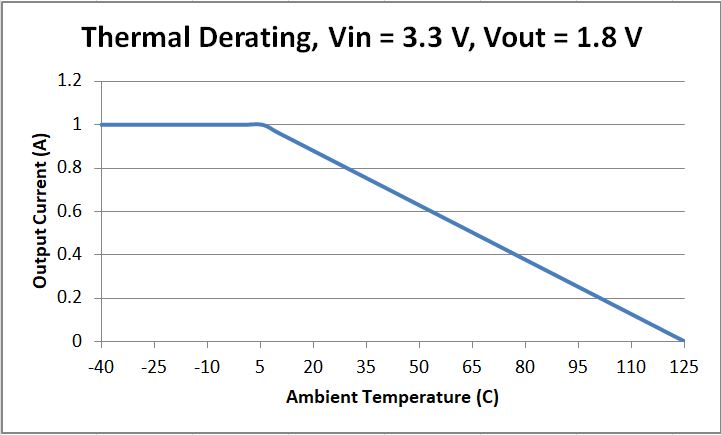
Some power IC datasheet will have the Thermal Derating Curve which will show how the output current/output power change when temperature rise.

For example,tps82140 has the following curve.

However, I can't find the curve in TPS7A88-Q1/TPS7A8101-Q datasheet. How can I know the Power Derating about these socket? Does any other Parameter or curve also describe Thermal Derating?

Thanks a lot !

  • Hi Amelie,

    This curve can be derived for the TPS7A88-Q1 with the θja parameter specified in the datasheet. Note that this LDO is a dual output device, so for these calculations I will assume both individual LDOs are being used equally. The junction temperature is therefore calculated as:

    Tj = Ta + θja * (2*Pd)

    Tj = junction temperature

    Ta = ambient temperature

    θja = junction-to-ambient thermal resistance

    Pd = power dissipation of one TPS7A88-Q1 pass FET

    After rearranging this equation to make Iout the dependent variable and Ta the dependent variable:

    Pd,max = (Tj,max - Ta) / (2*θja)

    Iout,max = (Tj,max - Ta)/(2*(Vin - Vout)*θja)

    For this example I will use the following conditions:

    Vin = 3.3 V

    Vout = 1.8 V

    Tj,max = 125 C

    θja = 39.8 C/W

    The thermal derating curve is the maximum rated output current (1 A for the TPS7A88-Q1) or the Iout,max calculation above, whichever is smaller. You can use graphing software like Excel to plot the curve across the recommended operating temperature. I have also attached the spreadsheet in which these conditions can be changed to see the effects on the curve. 

    Thermal Derating.xlsx

    Thanks,

    Gerard

  • Gerard,
    It helps a lot! Thanks!