A related question is a question created from another question. When the related question is created, it will be automatically linked to the original question.
If you have a related question, please click the "Ask a related question" button in the top right corner. The newly created question will be automatically linked to this question.
BUCK3 is the only buck converter in the LM10506 that cannot be disabled by SPI communication. You can set the voltage to the lowest value(see PSML Mode in datasheet), by changing the value in Register 0x00 by SPI communication. When Register Address 0x00 = 0x00, VDCDC3 = 0.7V but this method still requires you to populate the L2 inductor & input/output caps for BUCK3.
The alternate option would be to disconnect the DCDC3 converter in hardware. You can short VIN_B3 to GND, float SW_B3 pin, and short FB_B3 to VIN. This will keep the voltage at the feedback pin above the setpoint at all times and the PMIC will not see it as "out of regulation (below 85% of the output level)".
Unfortunately, I cannot test this on the LM10506EVAL board because the FB_B3 pin is on the inside of the BGA package.
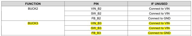
You should follow the datasheet recommendation. There must be a special provision in the LM10506 device that detects when FB_Bx is connected to GND so that it does not indicate that the DC-DC regulator is "out of regulation".
It is safe to connect VIN_Bx and SW_Bx to VIN directly, because they will be at the same potential. There is no risk for overcurrent with both the input and output at the same potential.