This thread has been locked.

If you have a related question, please click the "Ask a related question" button in the top right corner. The newly created question will be automatically linked to this question.

BQ25713: SCAP charging behaviour

Part Number: BQ25713
Other Parts Discussed in Thread: BQ25703A

I like to charge a series of 8 10F capacitors within less than 10 seconds.

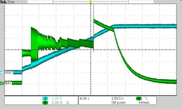
The Application Report SLUA913 for the similar charge controller BQ25703A describes the charging behaviour for SCAP's. Is this document also valid for the BQ25713?
Unfortunately the wake-up charge, a phase with a 0A charging current and the recharge phase slow down the charge sequence enormous.

Is it possible to charge or recharge the super capacitors only using the fast charge mode to reach charging or recharging times under 10 seconds?

  • Hello,

    Yes the document is also valid for the BQ25713.

    I would also suggest utilizing the battery only configuration of the charger that removes power path in order to achieve what you need. Section 9.6.5.1 System Voltage Regulation of the datasheet describes the configuration needed to achieve this such that the BATFET is removed from the circuit. Several bits and settings are needed, but from that there is not auto-wake up current nor is there the 0A charging phase.

    In testing, charge looks something like the following:

    You also need to consider how much power your input can provide. Depending on the voltage you need to charge the capacitor stack to, the current will change to meet the 10s charge time.And your input can potentially limit this if the power needed is too large.

    Regards,

    Joel H

  • Hi Joel

    Thank you for your answer.

    I have some more questions according to the oscilloscope print screen.

    The current on the screen shot seems to shows three phases:

    1. 5.8A for 2 second => What hapens here?
    2. about 7A for 14 seconds => This could be the prechage phase. Did you use a smaller Rsr of about 0.5mOhm to reach a 7A chaging current?
    3. 10A ramping down => This will be the fast charge phase. Is the current ramp down caused be the limited primary power?

    Regards,
    Adi

  • Hey Adi,

    Sorry for my late response. I will need to retake this waveform because I was unable to reproduce it. Let me do that and get back to you.


    Regards,
    Joel H
  • Hey Adi,

    So I was able to mostly replicate that waveform. In order to prevent very high ripple current to the output, there is a current clamp on the current delivered to the output while the battery voltage (here shorted to VSYS) is below a certain threshold.


    Regards,
    Joel H
  • Hi Joel

    Thank you for your answer beloning to my first question.
    Please let me know if my assumtions beloning to my second and third question are correct?

    Regards,
    Adi
  • Hey Adi,

    In this configuration, there is no pre-charge phase. This charge controller only limits current if the LDO enable option is on, which by default it is. However, for a super capacitor configuration like this one, you will want to disable this function. The LDO function mimics a "pre-charge" phase, but in reality it is only there is protect the PMOS BATFET. I shorted across BAT and SYS for this test which removed the need for the LDO mode.

    The current ramp down is due to the voltage on the supercapacitor approaching the programmed battery regulation voltage. This, in a battery configuration, would be called Constant Voltage (or CV) mode. Here, the output voltage of the charger is regulation to a voltage rather than regulating the current. In this state, the current is only dictated by the VSRN (programmed) - VCELL (supercap voltage) divided by the line resistance between those two nodes.


    Regards,
    Joel H