This thread has been locked.

If you have a related question, please click the "Ask a related question" button in the top right corner. The newly created question will be automatically linked to this question.

TPS92075: Schematic for 230Vac

Part Number: TPS92075

Hello,

I have to develop a new board.

Requirements are:

Input 230Vac, Triac (or IGBT) dimmable

Output: LED 12V, 500mA

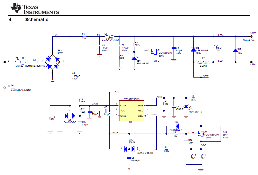
I follow TI PMP6016 eference design where I can see buck solution:

In TPS92075 datasheet and in TPS92075 DesignCalculator is suggested to use buck driver and angle sense configuration with straight resistor divider beetween LED+ and GND.

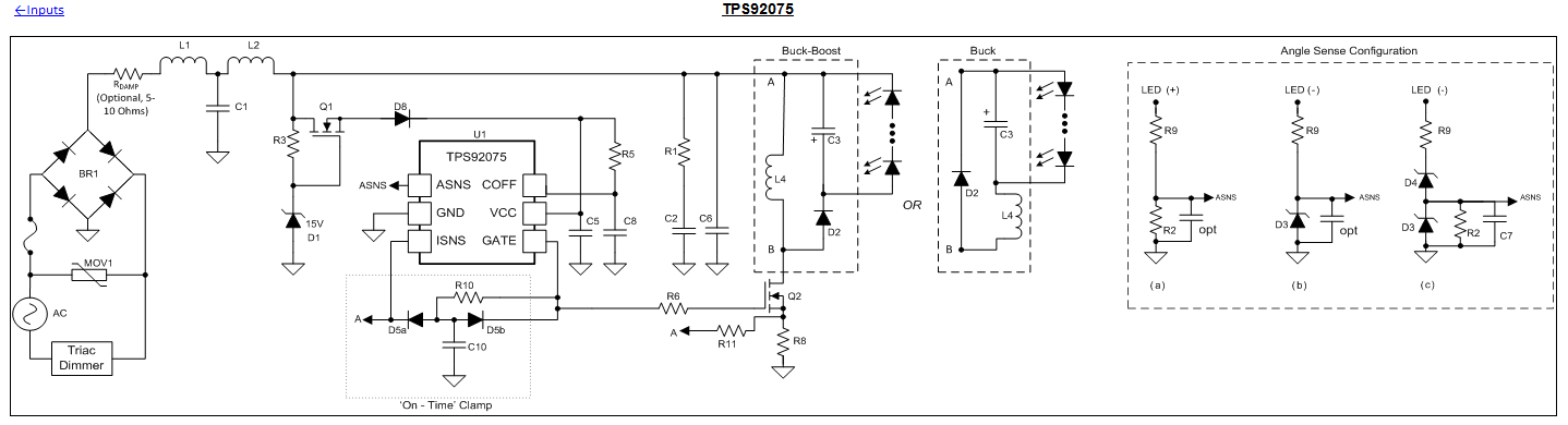
So, I can see that on Reference design "Angle sense Configuration" is a straight resistor divider beetween LED- and GND, not beetween LED+ and GND.

Why this difference?

What is the solution that I should follow?

Thank you

  • Hello,

    With a 12V led string it probably doesn't matter. The reason it was used from LED- is because the LED stack is 80V and a buck converter cannot pull current from the PFC capacitor when below 80V. This leaves LED+ at around 80V. If it's pulled from LED- it can get to GND. Note that it will change the angle sense sense points. Again at 12V it's not much different either way. If you use LED+ you will draw slightly more current when the input voltage is lower (sense point would be LED+ versus LED+ - 12V). At 6W load it may be difficult to make this work with many dimmers due to the holding current requirement. PFC and EMI capacitors need to be small and you may need a multiple stage EMI filter to keep the line capacitors small.

    Best Regards,
  • Hello,

    understood, thank you