This thread has been locked.

If you have a related question, please click the "Ask a related question" button in the top right corner. The newly created question will be automatically linked to this question.

UC2845: The duty ratio of UC2845

Part Number: UC2845
Other Parts Discussed in Thread: TL431

Hi E2E,

My customer use UC2845 to make a flyback. Vin=24V,6*Vout=24V,One 12V auxiliary winding output, oscillation frequency 220 khz, output frequency 110 khz, optocoupler feedback. They met a problem.

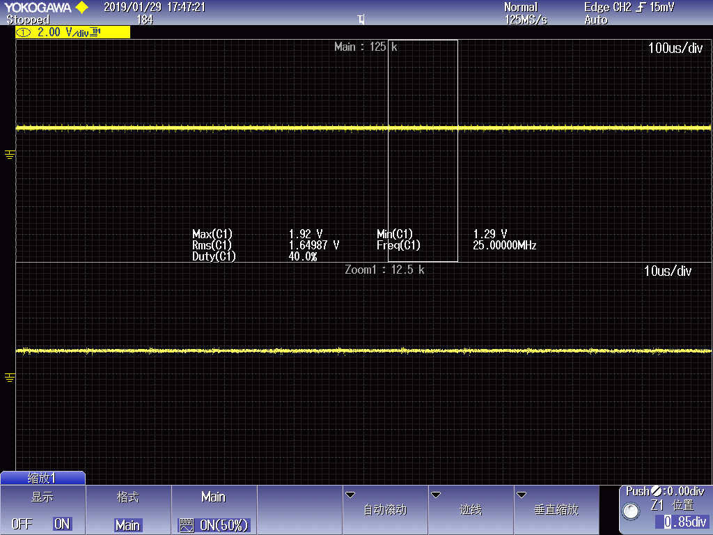
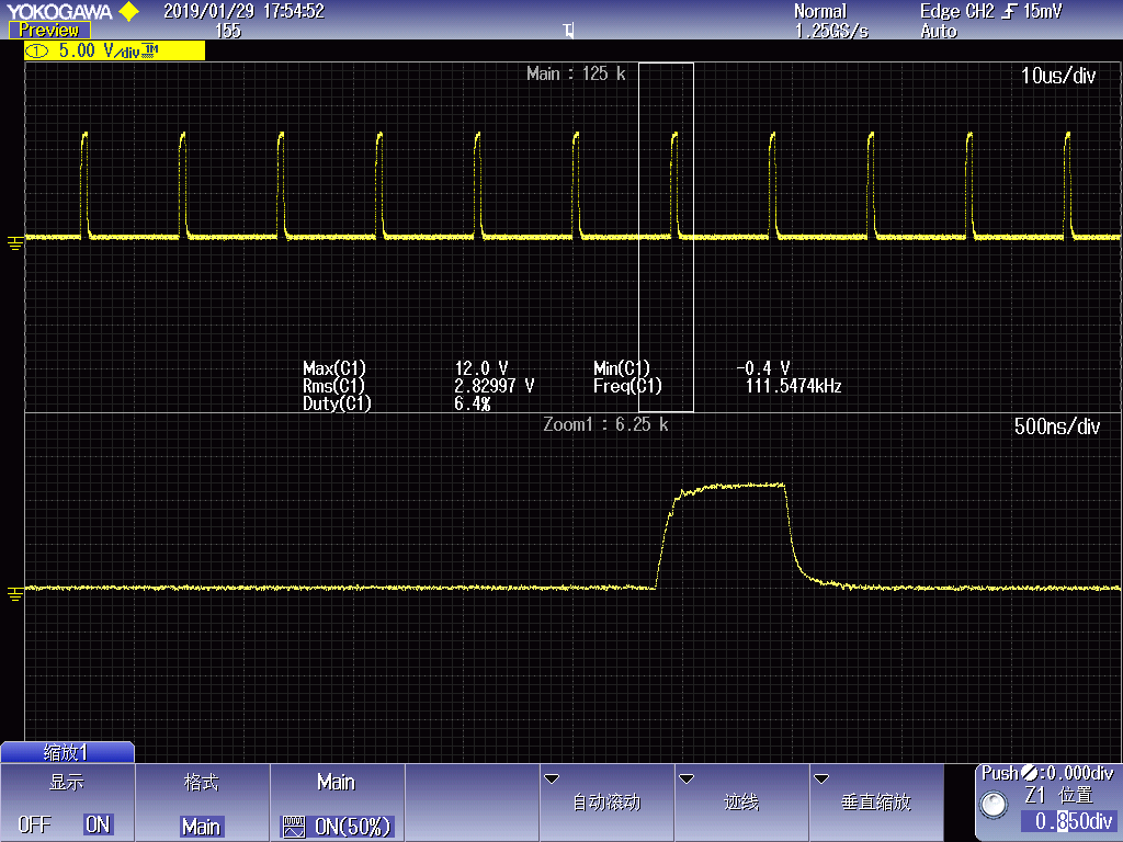
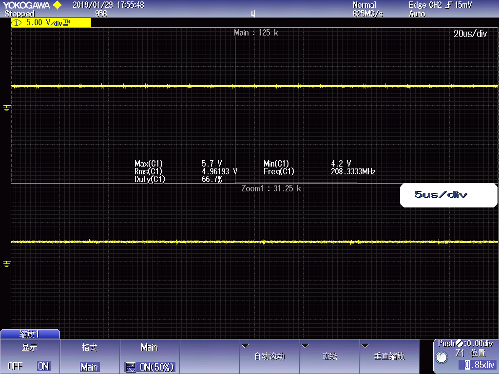
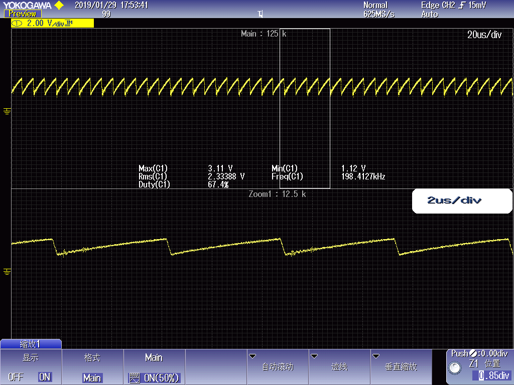
At present, the duty ratio of the transformer's input terminal is 4-11%, and the input and output power is small. We want to increase the duty ratio to increase the input and output power. However, several transformers have been replaced, and the duty ratio can not be adjusted (want to be adjusted to about 30%), basically maintained at about 9%, and the input power is about 8.6W. The schematic is as attachment.

7824.POWER.pdf

  • Hi Kun,

    Can you send some waveforms of the COMP pin, ISEN pin as well as the input voltage, output voltage and loading. I also need the transformer primary inductance.

    Thanks

    Peter
  • Hi Kun,

    Its been seven days since the last activity on this post, I hope you have made some progress in the meantime. I am going to close this post. If you have more questions please open a new post.

    Regards

    Peter
  • Hi Peter,

    Transformer output 24V and Vin 24V waveforms as attachments. Other pins waveforms have been damaged, please wait a little longer time.

    BRs

    KUN

  • hi Peter,

    The waveforms as attachments. Please refer ,thanks!

                                                                                                                 COM pin


                                            ISEN pin waveform


                        PWM OUT Pin waveform


                          VI waveform

                            VREF waveform

       Oscillation waveform

    Any you want, please let me know.

    BRs

    KUN

  • Hi Kun,

    The COMP pin voltage is about 1.6V, this voltage level is been set by the voltage control loop on the secondary side, based on the TL400 (TL431).

    As the load on the power supply increases there should be a small drop in the output voltage this should cause the TL431 to shunt less current so the voltage on pin 1 of the opto-coupler should rise as the output load is increased.

    Regards

    Peter
  • Hi Kun,

    I have seen that you opened a new post, please contniue to reply to this post if you have more questions.

    Have to checked to see if the voltage on the COMP pin varies with load?

    Thanks

    Peter
  • Hi Kun,

    Since there has been no activity on this post for over a week now I am going to close it. Please open a new post if you have more questions.

    Thanks

    Peter