This thread has been locked.

If you have a related question, please click the "Ask a related question" button in the top right corner. The newly created question will be automatically linked to this question.

TPS549D22EVM-784: How to configure the EVM when use DCAP mode?

Part Number: TPS549D22EVM-784
Other Parts Discussed in Thread: TPS549D22

Hi team,

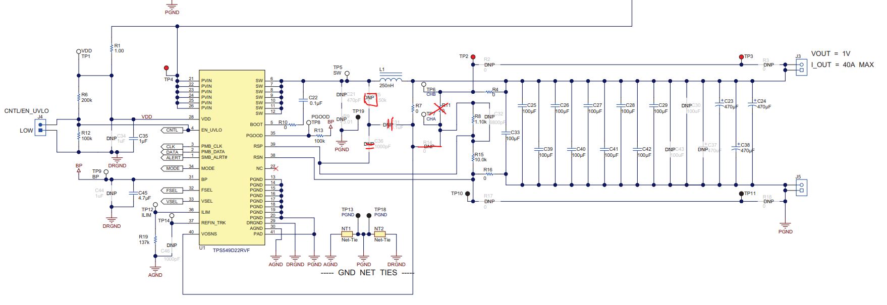
if my customer want to use DCAP mode of TPS549D22. How to configure the EVM? Whether we can do as the graph below. solder the RCC injectioncircuit, and remove the R11, solder R14, change R7 to 50ohm and inject to TP6 and TP7. Thanks.

  • Frank,

    For DCAP operation, first change R24 to the appropriate resistor value for the DCAP mode you desire.R5, C31 and C36 are the components you need to populate for ripple injection. I will need to get back to you on the bode plot measurement. I don't think you can readily measure it in DCAP mode. You may need to add a blue wire to it.
  • Frank,

    This EVM is not specifically set up for both DCAP operation and loop response measurement. The VOSNS pin is normally connected to Vout by the 0 ohm resistor R7. R7 also connects the C31 side of the ripple injection circuit to Vout. To measure the loop, the AC signal must be injected into both the VOSNS and RSP paths, So connect VOSNS to the bottom of R11 with a 0 ohm resistor installed at R14. Use your preferred FRA ac injection resistor (10 or 50 ohm) at R11. Now you will see that R11 is effectively shorted by the 0 ohm series resistance of R4 + R7 + R14, so R7 must be removed. Now the ripple injection circuit includes R14 + R11 in series with C31. R14 is 0 hm, but the resistance of R11 will avvect the waveform of the ripple injection circuit, making it more square wave than triangular in shape. I would recommend making your loop response in this configuration, then replace R7 = 0 ohm, R14 = DNP and R11 = 0 ohm for your remaining evaluation. Let me know if you have any issues.