Other Parts Discussed in Thread: TPS61252, TINA-TI
Hi,
I want to use the TPS3839 to monitor the voltage of a LiPo battery so that when the battery voltage drops down to 2.9V the boost coverter I'm using (TPS61252) goes into shut down mode.
The boost converter Enable pin has a logic high threshold of 1V.
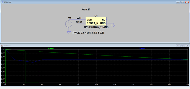
I have a doubt about the voltage level that the RESET pin of the TPS3839 assumes in its high logic state. Reading the datasheet of the component I thought that the RESET pin in its high logic state would simply track the voltage of the battery at the Vdd pin. But I've tried to simulate the component using the spice model on the TI website here ( http://www.ti.com/product/TPS3839 ) and it seems like the RESET pin voltage is being generated differently.
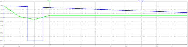
This is a simulation relative to the TPS3839G25 model with a 2.325V threshold voltage as an example. I've created a PWL waveform as the Vdd input. As you can see the RESET pin in its high logic state can assume a voltage higher than the Vdd value at the same time because it drops slower than Vdd.
Could you please explain how the RESET voltage is being generated by the TPS3839 when in its high logic state?
Thanks!