This thread has been locked.
If you have a related question, please click the "Ask a related question" button in the top right corner. The newly created question will be automatically linked to this question.
Hi,
We are working with inverter designing for motor drive application..
Our preferred IGBT is SKM100GB12T4. Its gate capacitance Qc = 565nC at Vge=-8V to 15V.
switching frequency : 20kHz, Gate resistance Rg = 10 Ohm, . Internal gate resistance : 7.5 Ohm
Average gate current : 11.3mA and peak gate current is 1.3714A
Power required per channel is 271.19mW.
1. Shall we use ISO5852S to drive this IGBT or do we required external gate current buffer circuit?
2. How to calculate the values for Rg (on) and Rg (off) in ISO5852S ?
Kindly confirm the details to proceed further.
Thanks & regards,
Rajasekaran
hi,
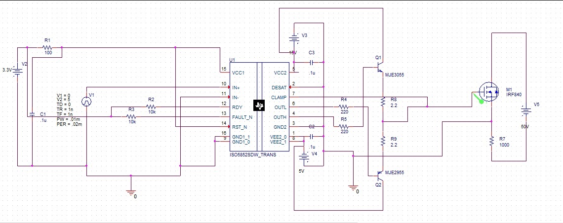
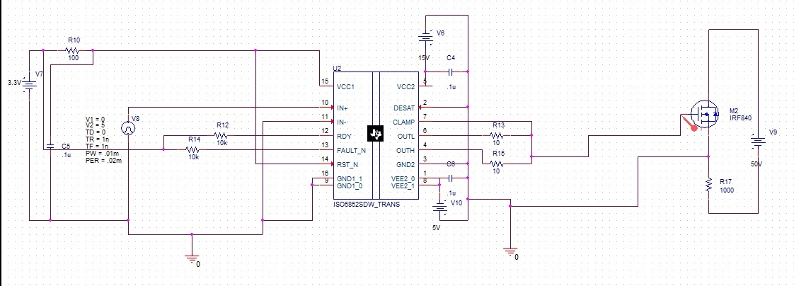
I am trying to simulate ISO5852S gate driver in Orcad PSPICE software. we created the circuits with and without current buffer circuit.
we used IRF840 switch and when we used current buffer circuit, it takes less gate current compared to without current buffer circuit. We need to replace the IRF840 with SKM100GB12T4 IGBT model.
circuit with current buffer
circuit without current buffer
(Red color for gate current without buffer circuit and green color for gate current with buffer circuit)
Could you please guide us the reason for the variation in the gate current (for same switch with same frequency & duty cycle)
Thanks & regards,
Rajasekaran