This thread has been locked.
If you have a related question, please click the "Ask a related question" button in the top right corner. The newly created question will be automatically linked to this question.
Hi there!
I'm developing a ignitionmodule for an older type jetski/ universal to older engines.
For this unit I've an huge band of input voltages going from 60-280VAC (and in worstcase more) after a long search on the internet I ended up with the UCC28911-chip and its reverence design.
After implementing the reverence design into my own design, and ordering/soldering the PCB, I cant get the powersupply to work properly..
the output voltage is about 1/2VDC and should be 5VDC.
when I remove the preload resistor, the voltage goes up to 5.2VDC, when I connect an LED to the output, the voltage drops to 2.4VDC and the LED starts blinking softly.
I'v tried changing the IPK resistor, as wel as the VDD resistor.
When hooked up to a scoop, I can see that the voltage on the VDD pin is going up and down between 10 and 5.2V, this wont change if change the inputvoltage (tested with 60VDC and 60-120VAC)
the drain is showing a wierd signal (see blue signal in the picture)
this signal is apearing when the VDD pin is at 10VDC, after this signal, the VDD-pin is slowly dropping to 5.2VDC and starting to go up to 10.2VDC quickly.
the used schematic:
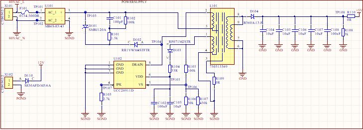
what is wrong with this schematic?
I've used reverence design when designing the PCB.
please help me!
Hello Midian,
Please share your design spec that will help me review your schematic. Also what is the transformer turns ratio. Looks like there is an under-voltage lockout fault and the aux winding is not generating enough energy to keep VDD high, this is evident because VDD falls down to VDDhv(on) threshold before attempting a restart.
For experimentation: you may disconnect VDD from the board and try to power it ext using a DC supply of 10V.
Regards,
Sonal
Hi Sonal,
After your first reply about a to low input voltage, I've added a capacitor I found (47uF) to the bridge rectivier and the circuit started up immediately!
It looks like its working fine now!
I've one question left: original the circuit started up at 82V and shuts of at 52V, after decreasing RS1 i managed to get the circuit to start up at 55V and shuts of at 42V, but the output voltage dropped to 4.2V...
So I thought I had to change the value of RS2 as wel, but then the output voltage did go up to 7.2V that day and the other day, it dropped back to 5V...
What can possibly cause this condition?
regards,
Midian