This thread has been locked.
If you have a related question, please click the "Ask a related question" button in the top right corner. The newly created question will be automatically linked to this question.
Hello,
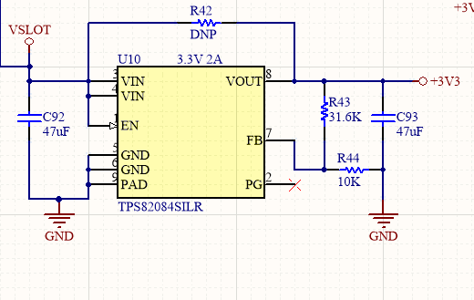
I have a design that uses TPS82084, to generate a 3.3V. The schematic is below. The input "VSLOT" is typically 3.3V. This circuit is designed to provide safe 3.3V to FPGA, as the FPGA can only tolerate 3.4V.
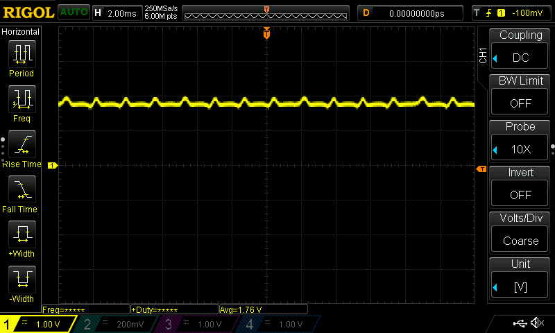
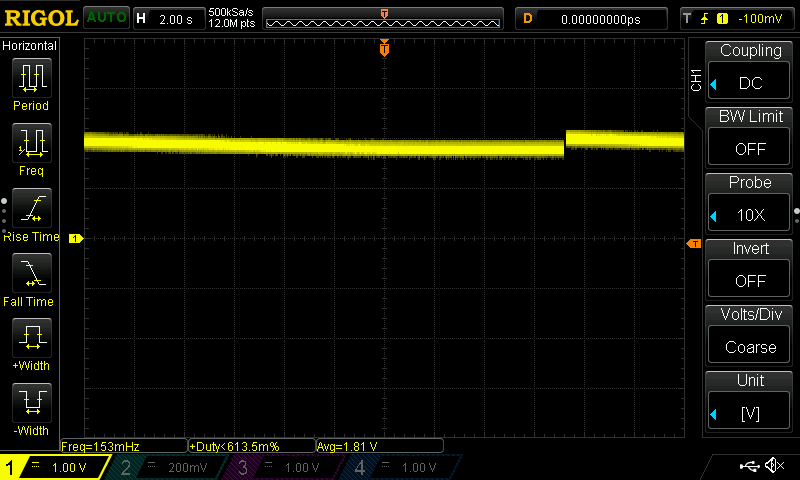
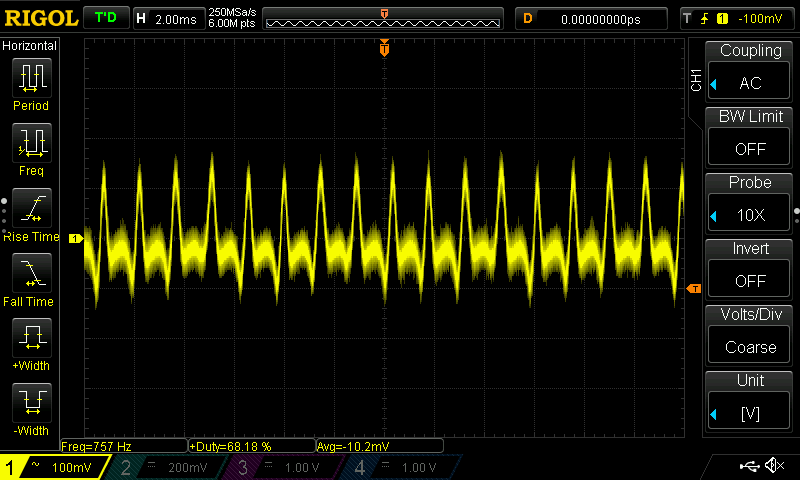
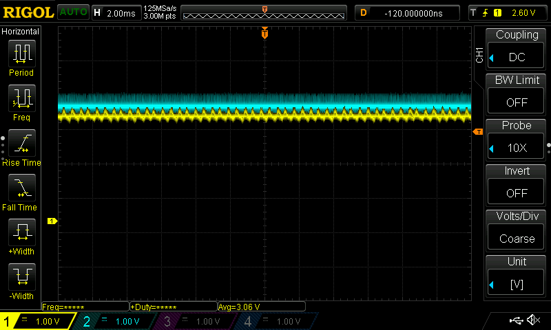
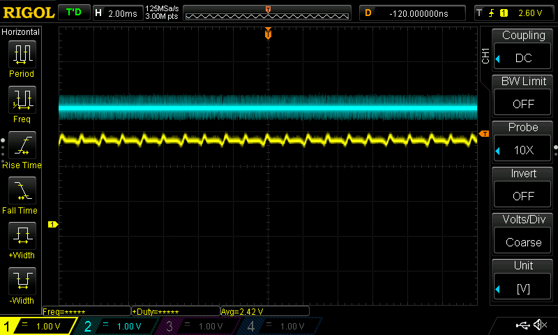
Anyway, what I'm seeing is that when VSLOT is very close to 3.3V (like 3.32-3.36V), the output of the 82084 slowly drops to 0V (over about 2 minutes). These is an additional 50uF of capacitance on the output (not shown). The supply is powering LEDs and other stuff, so its unlikely that it completely shut off.
This only happens when I power VSLOT with certain supplies. When I power VSLOT with a linear supply, this doesn't happen. Is the 82084 more susceptible to noise when it is near 100% duty cycle?
Thanks in advance!
Hi Dave,
Thanks for reaching out to us and please accept my apologies for replying late because of the weekend.
Please refer to this application note (www.ti.com/.../slyt747.pdf )to understand the 100% mode in our low-power DC/DC converters better.
Furthermore, can you please tell me what is your typical output current in your application and if you can provide the waveform for the input and output voltage and the type of supply you mean when you say "certain"?
Thanks!
Omar
VIN, DC coupled
The following are all VOUT of the 82084:
After voltage has dropped to ~1.7V:
Long term droop
Vout, AC coupled:
Hello Omar,
Thanks for the response. I'm certain the Vin is stable and constant. It has the ripple (shown in the AC waveform) but thats it. I can capture a trace with VIN and VOUT simultaneously.
I trued 0.1uF across VIN, it didn't change anything. I'll try 1uF.
The discharge behavior is this: VOUT is steady at about 3.110V for a while (like 30s), then it starts to drop slowly, like 1mV/s, then it speeds up, say to 10mV/s, until it gets to about 1.7V or so, where it drops slower, probably because the LEDs aren't on anymore. I don't know if the output actually goes all the way to 0V, I can check. I haven't waited that long.
Hello Omar,
I probed both sides of the inductor- never saw any switching. As such, both sides of the inductor look just like vout. The part starts up in 100% mode, apparently. I have verified that when I give it more vin, it does regulate. PG is unconnected. And, I only built one of these boards- so 1/1 have the problem. I use the 82084/5 all over the place (we've probably used over 20K of these parts without issue), but I've never used one in 100% mode.
Attached are more scopeshots. I'm showing vin and vout at the same time. Blue is vin, yellow is vout. Vin doesn't change, vout drops.
Notice that once vout starts dropping, some ripple appears. Its about 700Hz, which is very low. It seems like the part is trying to work, but it just can't. Like there isn't any charge for the upper fet.
Initial condition, at powerup. Vin has some ripple, but vout is the same and vin's average
After about 30s, vout is dropping, and has that weird waveform
After 1 minute: