This thread has been locked.

If you have a related question, please click the "Ask a related question" button in the top right corner. The newly created question will be automatically linked to this question.

ISO5452-Q1: ISO5452-Q1 DESAT time equation and clamp pin issue

Part Number: ISO5452-Q1

Hi E2E,

1 I have check the datasheet and I don't find the equation to calculate the DESAT time. Did I get something wrong?

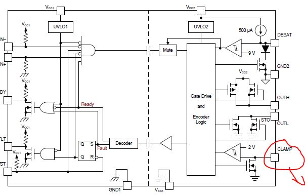
2 The clamp pin is not used , is this pin suspended?

3 I have a question that we need big source current to open MOSFET/IGBT quickly and a smaller sink current to close. Why our part have a small source current and a big sink current.

BRs,

Kun

  • Hello Kun,

    1. If you wish you calculate the DESAT blanking time, you can find it in Section 10.2.2.8. Re-arrange the equation in the text to find the timing (dt), where dVCE with the DESAT threshold voltage, which is 9V, C_D-DESAT is the blanking capacitance value you choose, and I_Charge is 0.5mA.

    2. If you do not need the Miller Clamp, you may leave that pin floating, as shown in Fig. 55.

    3. In many applications using IGBTs, there is a small tail during the turn-off transition. Thus, a larger sink current helps to reduce switching loss. If you wish to increase the source current in your application, you can use an external buffer as shown in Fig. 57. If you want to limit the turn-off current after adding the buffer, you may also have separated turn-on/turn-off resistors by adding a fast-recovery diode in series with the turn-on resistor. This will allow you to have larger turn-on source current versus the turn-off sink current.

    Regards,

    Audrey