Other Parts Discussed in Thread: LM74670-SQEVM, , TIDA-00858
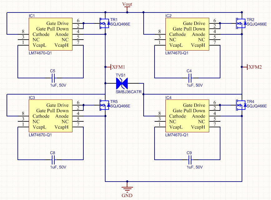
We evaluated the LM74670-Q1 with your development kit LM74670-SQEVM and at first glance it worked as expected for a single sided supply. However all our products require full wave rectification and so we created a circuit using 4x LM74670-Q1 in a bridge rectifier arrangement, similar to your TIDA-00858 and also Figure 11 in the LM74670-Q1data sheet, in order to evaluate the parts in that configuration. Please see the circuit diagram attached. XFM1/2 connect to a 100VA 15VAC transformer secondary. TVS1 was not fitted.
We first tested with a regulated DC source rather than the transformer and the circuit operated as expected. We then moved to using the AC supply. We had some success when using IRF740 as the MOSFETs but no success with some other versions including SQJ422EP (as found in the recommended MOSFET examples in Table 2 of the LM74670-Q1data sheet and used in LM74670-SQEVM ) - our circuit smoked quite quickly! Our original circuit contained SQJQ466E - which also did not work as expected.
In order to check our circuity we focused on one single quadrant of the bridge rectifier by removing three others. Our reasoning was to validate one quadrant first, then to add more progressively. We therefore re-created the test but removed IC1, IC2, IC4 and their surrounding parts. We left the transformer connected to XFM1, removed the other side of the transformer from XFM 2 and attached it to GND through a 200R load. This is then effectively just the smart diode and 200R across the transformer secondary. We monitored current through the load and the gate of IC3. With an IRF740 we saw results similar to what we expected with the gate being driven and the load conducting on every other half cycle (except for some half cycles where the gate was not driven while the body diode was conducting during the charging of C8); with the SQJ422EP the gate was constantly driven (except during those periods while the body diode was conducting during the charging of C8) and the load continuously conducting.
Our finding was that the difference in Rds(on) was the differentiating factor. The IRF740 has a Rds of 0.55R, the SQJ422EP has a Rds 4.3mR. This Rds determines the voltage drop across the FET, and therefore the voltage between the Anode and Cathode pins on the LM74670. When the smart diode configuration is forward biased this presents no problem, but when reverse biased we note that the smart diode does not stop conducting until the LM74670 detects -20mV between the Anode and Cathode pins. For a Rds of 0.55R this corresponds to 36mA of current through the MOSFET - an amount that in the context of a high current power supply can be passed off as a form of "waste" or "leakage." However with a Rds of 4.3mR over 4.5A is required to create the -20mV drop across the FET - a large current indeed!
We manually inserted resistance in series with the SQJ422EP channel to verify that increased "Rds" did indeed generate the -20mV sooner and stop conduction of the smart diode.
We now understand why the smart diodes worked with single sided supplies - as there is no need to switch off since the -20mV will never be generated.
We do not understand how this is to work in a practical arrangement with a full bridge rectifier. An increase in Rds will remove any efficiencies that the smart diode should produce over standard diodes. In any event we do not understand how your solution TIDA-00858 works at all.
We would like to evaluate your solution TIDA-00858 but note that there is no development kit built for this. We are eager to create a replica of your solution in order to validate its performance but would appreciate a comment on our findings above first in order to give us direction in our investigations as we are now at an impasse on understanding how this circuit will operate properly.
Your comments would be most appreciated.