This thread has been locked.

If you have a related question, please click the "Ask a related question" button in the top right corner. The newly created question will be automatically linked to this question.

UCC28951-Q1: UCC27424 DRIVER CHANGE THE PIN VOLTAGE AS SHOWN.

Part Number: UCC28951-Q1
Other Parts Discussed in Thread: UCC27424,


                                              NOTE THE CHANGE IN VOLTAGES WHEN DRIVERS ARE INSTALLED.

No Drivers Installed

Q1,Q2 and Q3,Q4 Drivers Installed

No Drivers Installed

Q1,Q2 and Q3,Q4 Drivers Installed

Vref

1

5.60

7.40

GND

24

0.00

0.00

EA+

2

2.80

4.00

VDD

23

10.20

10.20

EA-

3

0.40

0.60

OUTA

22

10.20

10.20

Comp

4

4.80

6.80

OUTA

21

10.20

10.20

SS/EN

5

5.00

7.20

OUTC

20

10.20

10.20

DELAB

6

0.80

0.80

OUTD

19

10.20

10.20

DELCD

7

0.80

0.80

OUTE

18

0.40

0.40

DELEF

8

3.00

4.00

OUTF

17

0.40

0.40

TMIN

9

1.40

1.40

SYNC

16

4.60

6.20

RT

10

2.80

4.00

CS

15

0.40

0.60

RSUM

11

2.80

4.00

ADEL

14

0.40

0.60

DCM

12

0.80

.800

ADELEF

13

0.40

0.60


WHEN NO DRIVERS ARE INSTALLED I HAVE 12 VOLT SIGNALS ON OUTA, OUTB, OUTC, OUTD.

WHEN DRIVERS ARE INSTALLED I HAVE TO LOWER THE VOLTGE TO 10 VOLTS . WHEN LEFT AT 12 VOLTS THE SIGNALIS SKIPPING POLSES AND THE DUTY CYCLE VARIES FROM 40khZ TO 60KHz. WHENVOLTAGE IS DROPPED TO 10 VOLT THE SIGNAL STAYS AT 100KHz.

THE DRIVERS ARE UCC27424. THE DRIVERS ARE RIVING GATE DRIVE TRANSFORMER. THE SIGNALS ARE IDENTICAL TO THE DRIVER WAVEFORMS.

Question: Why are the drivers changing the waveforms this way?

  • Hello Eddie

    You said "WHEN DRIVERS ARE INSTALLED I HAVE TO LOWER THE VOLTGE TO 10 VOLTS . WHEN LEFT AT 12 VOLTS THE SIGNALIS SKIPPING POLSES AND THE DUTY CYCLE VARIES FROM 40khZ TO 60KHz. WHENVOLTAGE IS DROPPED TO 10 VOLT THE SIGNAL STAYS AT 100KHz."

    Please clarify which signals are skipping - are the signals at the OUTA, OUTB, OUTC and OUTD pins skipping or are they ok and it is the output from the UCC27424 driver which is skipping ?

    Can you post some waveforms here showing one of the driver inputs and its output during this skipping - OUTA_in and OUTA_out for example.

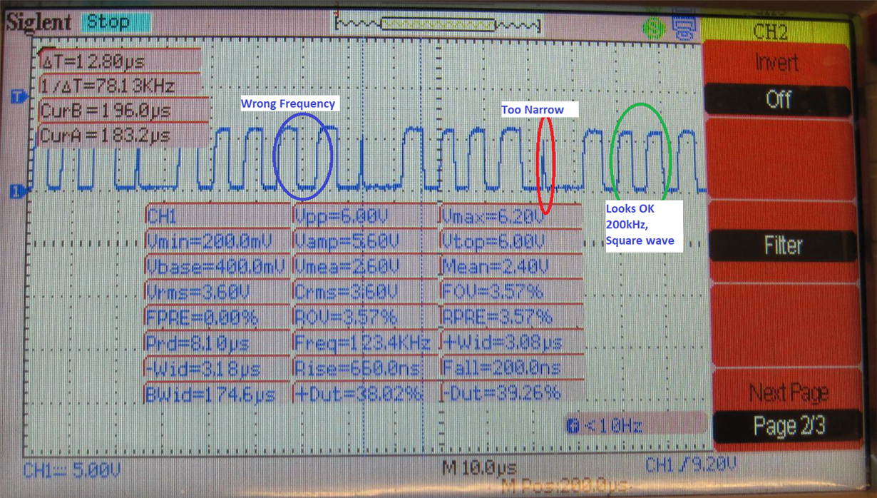
    I presume you mean that the frequency varies from 40kHz to 60kHz rather than the duty cycle. Please check the signal at the SYNC pin of the UCC28951-Q1 device. This is derived from the internal clock of the controller. It should be a constant 200kHz (2 x switching frequency)

    What is the VCC level on the UCC27424 - is it the same as that on the UCC28951-Q1 ?

    Have you looked at the OUTx signal waveforms at the input pins to the driver - are they distorted or noisy ?

    The first thing to figure out is whether this is an issue with the controller or with the driver - the checks above should help.

    Regards
    Colin
  • FIGURE 1 UCC28951-Q1 Sync (Pin 16)

    FIGURE 2 -  UCC28951-Q1 DRIVER B (Q3, Q4) – DRIVER A (Q1, Q2) NOT INSTALLED

    BLUE SIGNAL (Q3) DRIVER OUTPUT SIGNAL

    RED SIGNAL (Q4) DRIVER OUTPUT SIGNAL

    FIGURE 3 -  UCC28951-Q1 DRIVER B (Q3, Q4) – DRIVER A (Q1, Q2) NOT INSTALLED

    BLUE SIGNAL (Q3) DRIVER INPUT SIGNAL

    RED SIGNAL (Q4) DRIVER INPUT SIGNAL


    FIGURE 4 -  UCC28951-Q1 DRIVER A (Q1, Q2) – DRIVER A INSTALLED

    BLUE SIGNAL (Q1) PIN #2 DRIVER INPUT SIGNAL

    RED SIGNAL (Q2) PIN #4 DRIVER INPUT SIGNAL


    FIGURE 5 -  UCC28951-Q1 DRIVER A (Q1, Q2) – DRIVER A INSTALLED

    BLUE SIGNAL (Q1) PIN #7 DRIVER OUTPUT SIGNAL

    RED SIGNAL (Q2) PIN #5 DRIVER OUTPUT SIGNAL


    FIGURE #6  --  UCC28951-Q1 IC SIGNAL SCHEMATIC

    TEST Chart.pdf

  • FIGURE 1 UCC28951-Q1 Sync (Pin 16)


    FIGURE 2 - UCC28951-Q1 DRIVER B (Q3, Q4) – DRIVER A (Q1, Q2) NOT INSTALLED

    BLUE SIGNAL (Q3) DRIVER OUTPUT SIGNAL

    RED SIGNAL (Q4) DRIVER OUTPUT SIGNAL


    FIGURE 3 - UCC28951-Q1 DRIVER B (Q3, Q4) – DRIVER A (Q1, Q2) NOT INSTALLED

    BLUE SIGNAL (Q3) DRIVER INPUT SIGNAL

    RED SIGNAL (Q4) DRIVER INPUT SIGNAL


    MORE ON NEXT REPLY


  • /cfs-file/__key/communityserver-components-multipleuploadfilemanager/7154b951_2D00_99f9_2D00_4694_2D00_a23b_2D00_2934a5ef6f2c-78544-complete/UCC28951_2D00_Q1-DRIVER-SIGNALS.pdf

    I HAD ALL THE SIGNAL SHOWING, THEN WHEN I POSTED, THEY DISAPPEARED.

    THE ABOVE LINK SHOW ALL THE WAVEFORMS (INPUT & OUTPUT) FOR THE UCC27424 DRIVER.

    THE PROBLEM I AM HAVING IS THAT EVERTME I INSET THE DRIVER FOR Q1,Q2  VOLTAGES AT THE UCC28951-Q1 RISE ABOUT 2V. IE PIN #1 Vref 5.25 V TO 7.4 VOLT..


    THE NEXT UPLOADES FILE IS A SPREADSHEET WHICH SHOWS THE CHANGE IN VOLTAGES WITH BOTH DRIVERS INDTALLED, NO DRIVERS INSTALLED, ONLY DRIVER A INATALLED  AND ONLY DRIVER B INSTALLED.

    IS THE UCC27424 NOT THE CORRECT DRIVER, IF NOY THEN WHAT WOULD E A ACCEPTALE DRIVER..

    I CANNOT FIGURE OUT WHAT IS CAUSING THIS PROBLRM.

    ANY SUGGESTION WILL BE WELCOME.

    SEE ATTACHED BELOW.


    NOTE:

    COLOUM 1 & 5 "W/ab ON" MEANS -- (DRIVER "A&B" INSTALLED)

    COLOUM 2 & 6 "W/ab OFF" MEANS -- (DRIVER "A&B" NOT INSTALLED)

    COLOUM 3 & 7 "W/DRV A ONLY" MEANS -- (ONLY DRIVER A  INSTALLED)

    COLOUM 4 & 8 "W/DRV B ONLY" MEANS -- (ONLY DRIVER B  INSTALLED)


    /cfs-file/__key/communityserver-discussions-components-files/196/7701.TEST-Chart.pdf

  • Hello Eddie

    I'm afraid that the user interface on this tool is not wonderful and I have also had images disappear when I posted an image even when they were clearly visible to me when I pressed the 'Post' button.

    Thanks for posting the images a second time - I had a look at them and I would think the following

    1/ VREF should never be greater than 5V and I don't know of any condition where it could increase to 7V or so except some general comment about noise on the ground pin, but I know that's not very helpful at this point.

    2/ The SYNC pin output should be a square wave at 2 times the switching frequency - in your case it should be running at a constant 200kHz for your switching frequency of 100kHz. The image you posted shows a signal with a lot of distortion and its amplitude is wrong - it should be 0/VREF or 0/5V but it is 0/7V indicating that VREF is too high - as you have noted.

    The first thing to do is to get correct operation of the UCC28951-Q1. I'd disconnect the drivers and run the controller from a 12V rail. In this open loop condition the controller should operate at Dmax  but at least you will be able to debug and correct the VREF and SYNC issues.

    I'd strongly suspect that there is an issue with your PCB layout - please post it here or send it to me at colingillmor@ti.com

    I'm travelling next week so there may be a delay in my reply

    Regards
    Colin

  • HI COLIN,

    THANK YOU FOR THE FAST RESPONCE AND FOR YOUR REPLY.  I'LL GET ACK WITH YOU IN A WEEK, WHICH IS ABOUT THE TIME I WILL NEED TO DIGEST YOUR RESPONCE AND EITHER FIND THE SOLUTION OR HAVE MORE QUESTIONS.

    ALSO I FOUND THE ANSWER TO THE PREVIOUS BATCH OF IC' BURNING UP AT PIN 23 AND OIN 24.  YOU' WILL NOT ELIEVE THIS.  I FINALLY DECIDED TO CUT THE IC OFF THR BOARD AND YOU PROBALLY ALREADY KNOW THE ANSWER, YUP FLUX.  ALL OF THE FAILLED IC's HAD FLUX UNDER THE IC.  I CONFRONTED THIS PERSON, EXPRESS WHAT I THOUGHT OF HIM, DEMANDED MY MONEY BACK, SAID A COUPLE OF VULGAR WORDS.  CAN YOU IMAGINE THAT, HE LEFT FLUX UNDER THE IC.  THAT GREATLY MADE ME UPSET. 

    FOUND ANOTHER PERSON AND THE FIRST IC ISTALLED WORKED.  A LESSOM LEARNED.

    ANYWAY, ENJOY YOUR TRIP AND WILL BE TALKING TO YOU AGAIN IN ABOUT A WEEK..

    ED LOY

  • Hi Eddie

    That's good news - at least finding out the cause of the IC burning up is good news although I know it cost you a lot of wasted time.

    I'll close this thread and please feel free to open a new one if you need to.

    Regards
    Colin