This thread has been locked.
If you have a related question, please click the "Ask a related question" button in the top right corner. The newly created question will be automatically linked to this question.
Hi team,
My customer is evaluating TPS62561 and TPS62743.
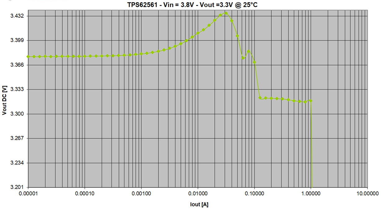
For TPS62561, the input is 3.8V and the output is 3.3V. Customer wants to know the output voltage when @ maximum 600mA output current.
For TPS62743, the input is 3.8V and output is 1.8V and 1.2V. Customer wants to know the output voltage of 1.8V and 1.2V setup when @ maximum 300mA output current.
I searched the datasheet of these 2 devices but only TPS62743 provides the load regulation data under VOUT = 1.8V condition. So could you please help provide the data that customer requires? Do we have a curve to show the relationship between Iout and Vout? Thanks.
Best regards,
Wayne
Hi Omar,
Thanks for your reply. But do you have the Vout-Iout curve of TPS62743 @Vin=3.8V and Vout=1.8V? I am asking because the 1.8V output is for a processor and the minimum requirement by the processor for this 1.8V rail is 1.75V.
So customer also did the test on their own. They use a digital multi-meter to measure the VOS pin voltage. They keep monitoring the VOS voltage as they increase the output current with a electronic load. They found that when the VOS drops down to 1.75V, the output current is only about 200mA. But according to our datasheet, the load regulation data is 0.001%/mA. This is not matching with the test phenomenon. So do you have any advice on this? If you could provide the Vout-Iout curve@Vin=3.8V and Vout=1.8V, that could be a reference. Thanks.
Best regards,
Wayne
Hi Wayne,
Thanks for the clarification.
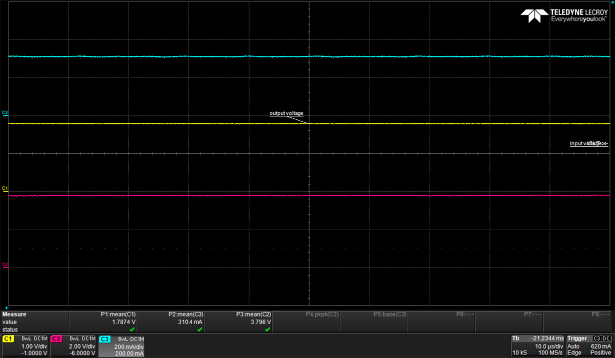
I, unfortunately, do not have validation data for Vout=1.8 at the moment. However, I went to the lab today and I checked the device at the conditions you mentioned: Vin=3.8V, Vout=1.8V, Iout=300mA, and the device operated as expected and described in the DS. The load current was increased from 60uA gradually to 310mA and no abnormalities were found with voltage regulations. Here is a waveform for the measurements:
I am not sure where the source of the issue would be at the customer side. Do you have the schematics and the layout of the design?
Maybe they can also try a different way of drawing current (a different electronic load maybe, etc.)
Best regards,
Omar