This thread has been locked.

If you have a related question, please click the "Ask a related question" button in the top right corner. The newly created question will be automatically linked to this question.

TPS2561: USB2.0 requirement

Part Number: TPS2561
Other Parts Discussed in Thread: TPS2557

Hi team,

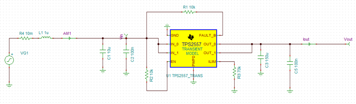
I want to use TPS2561 as a current limited power switch and can auto retry, there is no battery in the schematic, there are some DC/DC and MCU in the schematic. The USB port  connect to the computer, USB provides power and communication with MCU. The schematic is as below, please review, thank you.

1.whether TPS2561 can withstand normal plugging and unplugging the USB cable which connected with computer?

2.Does TPS2561 can meet USB 2.0 surge requirements?

  • Hi Kevin,

    Can't see your attachment.

    TPS2561 is a power swich. I am not so clear your point ' withstand normal plugging and unplugging the USB cable which connected with computer'.

    You mean the mechanical issue?

    TPS2561 has theporgrammable current limit function from 250mA to 2.8A. For the surge reqirement, please set the current limit value according to your application.

    If any other issue, please contact me any time.

    If you think this is your answer, please click'Issue is solved' button.

    Thanks.

    Ziv

  • Hi Ziv,
    Thanks for your quick feedback, I have uploaded the schematic, please review, the normal operation current of the pcba is 150mA max.

    The usb(JP1) of pcba connect with the usb port of computer by a usb cable.

    Does the TPS2561 support to hot swap, I want to plug and unplug the usb cable usually, will the TPS2561 be damaged? thank you.

    kevin

    SCHEMATIC_usb.pdf

  • Hi Kevin,

    Interesting application. Use as UFP, right?

    Yes, TPS2561 can support hot swap. It's just  a power switch.

    But, as hot swap, will generate the current/voltage overshoot, should confirm if it's ok for MCU.

    If you have big concern with this, you can send me the hardware to me. I can have a test for you.

    Please leave your email address to me. I can contact you.

    If any, contact me any time.

    If you think this is your answer, please click 'issue is solved' button.

    Thanks.

    Ziv

  • Hi Ziv,
    Thanks for your quick feedback.
    Yes, I use as UFP.
    The absolute maximum input voltage of TPS2561 is 7V in the datasheet, I have concern is that when I hot swap the usb, the surge voltage on the input of TPS2561 can damage the TPS2561 or not?
    Due to the turn on time delay on the TPS2561 and the current is limit by TPS2561 when power on,the maximum voltage on the MCU is 6.5V, I think the MCU can work normal on the hot swap condition,
    please help to simulation the schematic which I upload before, the load of TPS2561 is 150mA max,
    Thank you.
    Kevin

  • Hi Kevin,

    I think the surge voltage related to the cable length.
    I am not sure how much current the MCU will sink as hot swap. It's better to send me your hardware to me.
    I will have a test with different cable length and tell you the results later.
    If you have the hardware, I can also send you some samles to test.

    Please help close another same quesion on E2E named 'TPS2561: USB 2.0 plug'.
    I think will take some time to validate this. You can also close this quesion first by click'Issue is solved' button.
    I will reply to you by email. Please offer me your email address.
    If any other concern, contact me any time.
    Thanks.
  • Hi Ziv,

    Thanks for your support.

    The MCU will sink  about 50mA current in this schematic,I have no hardware yet.

    Since TI have advanced simulation tools and a strong technical team,

    Could you help to simulate the results of the usb cable length of 0.5 meters,1.0 meters,1.5 meters and 2.0 meters?

    Please evaluate whether the chip of TPS2561 can work normally in the situations as above?

    Thanks

    Kevin

  • Hi Kevin,

    Will reply to you thursday or friday.

    Thanks.

    Ziv

  • Hi Ziv,

    Thanks for your support.

    When you are simulating, you can  adjust the value of input and output capacitors of the TPS2561 , until the circuit meet the USB2.0 hot swap, the circuit  work normally.

    Thanks.

    Kevin

  • Hi Kevin,

    Sorry for the late reply.

    I test TPS2561 on EVM board and have a simulation by TI simulation tool TINA.

    The results are as following.

    1. 1m cable:


    2. 2m USB cable

    Conclusion: Have almost no overshoot. I measure the slew rate of hot swap of VIN. It's about 1V/10us. I think the slow slew rate also one reason without overshoot. i also consider the cable parasitic inductance which should cause oscillating. But from the results, there is no overshoot. From the results, seems like no need to worry the overshoot. But this results are just for referrence and not guaranteed due to different application scenario with differnent cable. No need to consider the output capcitor. Because as enabled, after about 5ms to turn on the switch.

    3. simulation results: don't have TPS2561 model. Use TPS2557 instead.

    With same slew rate of VIN as hot swap.

    With estimated parasitic inductance and resistor.

    The results have small overshoot.

    For your reference. If any other concern, contact me any time.

    If  you think this is your answer, please click'Issue is solved button.

    Thanks.

    Ziv'

  • Hi Ziv,

    Thanks for your support.

    TPS2561 is  as a device in this application, the input capacitance is relative to the inrush current and overshoot when hot swap,

    since the usb2.0 require the inrush current, could you  help to simulate the input capacitance of TPS2561 can meet the usb2.0 inrush requirement when hot swap.

    You are experts in usb, could you give me some advice, how much the input capacitance can meet he usb2.0 standard?

    thank you. 

    kevin

  • Hi Kevin,

    For the current protection, maily focus on hub and host protection. The power switch at DFP has current limit function.

    In my opinion, for the UFP mainly focus on their own normally function, such as the input capacitor to stablize the input voltage.

    Of cause, if we caculate the inrush current by 10uF with 1V/10us slew rate, the irush current is 1A.

    Just for your reference.

    If any, contact me any time.

    If this is your answer, please click'Issue is solved' button.

    Thanks.

    Ziv

  • Hi Ziv,

    Thanks for your support.

    kevin