This thread has been locked.

If you have a related question, please click the "Ask a related question" button in the top right corner. The newly created question will be automatically linked to this question.

TPS22946: Failed to switch on after EN signal applied

Part Number: TPS22946

Hello,

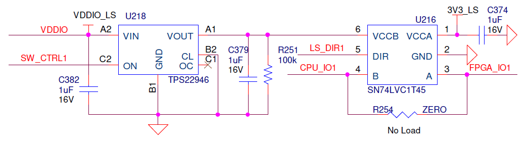
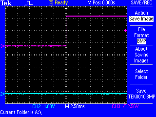
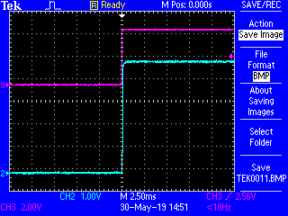
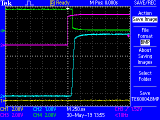
We're using a large number of TPS22946 (280psc) to control power supply for level shifters in our signal multiplexer design. And we observe that some of the switches are not turning on once EN signal is applied. It happens sporadically on 3-10 channels out of 280. When probing with oscilloscope, once EN is set, there seem to be no signs of overcurrent protection, voltage stays zero. After couple of power cycles the issue for particular channel resolves and correct operation can be observed. But later on it comes back again.

In our design we're not using OC output and it is left floating. Can it be related to the issue we observe?

Thank you for any information.

Best Regards,

Oleksandr

  • Hi Oleksandr,

    Thanks for reaching out on E2E!

    Can you share any oscilloscope shots or schematics of the configuration? How much load capacitance do you have? Have you been able to repeat the same tests with an output load?

    Thanks,

    Arthur Huang


    To find the latest information on Power Switches, visit www.ti.com/powerswitch

    Please click "This resolved my issue" button if this post answers your question.

  • Hi Arthur,

    Thank you for quick response. 

    The output load is 1 uF. I've attached the schematic of a single channel.

    Unfortunately, I have no oscilloscope shots yet, it's quite hard to catch the problem because of its sporadic behavior and lack of test points. But team is working on it and I hope to get some soon.

    Best Regards,

    Oleksandr

  • Hi Oleksandr,

    Thanks for the schematic. At first glance, I don't see anything wrong with the configuration. Please let me know when the team is able to collect some scope shots of the behavior.

    Have you been able to disconnect the downstream load and repeat the test? Does the same behavior occur?

    Thanks,
    Arthur
  • Hi Arthur,

    I've got the scope shots. One is for failure case and second one is expected behavior on the same channel after a power cycle. Channel 3 is ON signal and channel 2 is the output voltage. For the expected case I can see normal load capacitor charge, but in case of failure there is nothing on the output. Seems that part is latched up and does not react on the ON signal at all. We didn't try disconnecting a load, this require level shifter to be removed.

    Best Regards,

    Oleksandr

  • Hi Oleksandr,

    Can you zoom in on the rise time and also include a current probe? Also, are you able to repeat the test with the downstream load disconnected?

    Thanks,
    Arthur
  • Hi Arthur,

    Here's the zoomed-in shot. Rise time is as per datasheet. Channel 4 is the level shifter output signal. Unfortunately, our design does not allow using a current probe, layout is very tight and there are no points to connect. We'll consider removing a level shifter and capacitor on the output side to eliminate the load impact.

    Best Regards,

    Oleksandr

  • I found the root cause. There was parasitic current leaking into power supply rails when power is off causing input voltage ~1 V on the load switch input. It caused the switch to latch up and fail to respond to ON signal once normal power supply voltage is applied.

    Thank you very much for support.