This thread has been locked.

If you have a related question, please click the "Ask a related question" button in the top right corner. The newly created question will be automatically linked to this question.

TPS65265: TPS65265 Enable issue

Part Number: TPS65265

Hi Team,

My customer is using TPS65265 and has some concerns about the enable function.

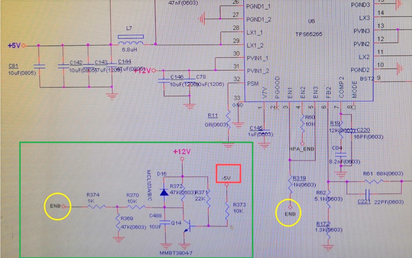
1. TPS65265 can start up normally with EN pin open or external 5V signal.

2. TPS65265 cannot start up by customer's external transistor control circuit (green square), which aims to enable the TPS65265 after the -5V supply's start up. Using this external circuit, the EN pin voltage is around 0.7V.

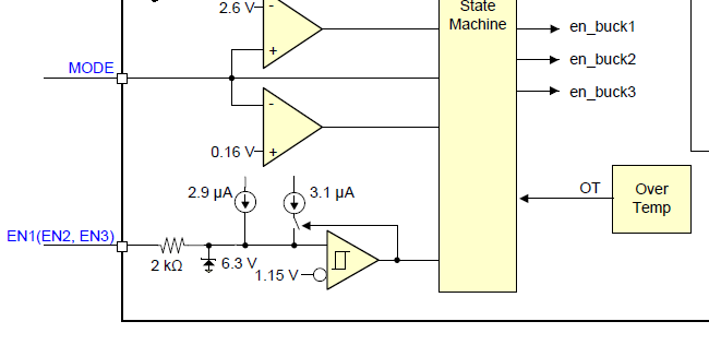
I notice that in datasheet [Page 16: The EN pin has an internal pullup current source, allowing the user to float the EN pin for enabling the device. If an application requires controlling the EN pin, use open drain or open collector output logic to interface with the pin.]

The question is,  what else circuit inside the Enable function block to let this  transistor control circuit fail? or we say, why this cannot work?

Please help, or have you met some similar applications? 

Thanks a lot.

Yang

  • Hi, Yang

    1. There are just 2 pull-up current sources at EN1/2/3 pin, see below.

    I think the internal circuit will not cause this issue.  

    2. I think the Q14 probably is not turned off completely when -5V startup.

     Suggest to some tests:

    1. Remove R319, power on, measure the ENB voltage again.

    2. And measure Q14's base and collector voltage.

    3. Change R371 to 35kohm, then measure Q14's base and collector voltage again.

    If collector voltage become high level, mount R319, the TPS65265 will start to work.

  • Hi Zhao,

    Thanks for your reply. I will ask customer to take a try.

    Yang