

We are testing a prototype we made using TI reference design docs for the BQ51013 Qi receiver. We followed a reference design from the SLUUA44A user's guide for the bq51013xEVM-764 evaluation module. Qi receiver schematic attached. We are currently testing using a 15W transmitter unit made by Wurth Electronics that has Foreign Object Detection. The Wurth transmitter is not a requirement, it is just what we had on hand to test with. We have a custom coil on the Rx side, made up from a flex circuit with copper etched into the shape of a receiver coil, similar to the geometry of the original Rx coil provided by the Wurth dev kit.
We are just looking for guidance on where to look/test based on details below. The end application is a small wearable to be tested for military use.
When we place the Rx circuit (schematic attached) over the 15W transmitter, we see the green LED in our circuit come on briefly which tells us the TI Qi receiver module is generating a voltage on its output line. But the transmitter detects a foreign object in a few seconds and stops transmitting. We know this because the transmitter blinks a red LED on the board, and the datasheet identifies that as FOD. We are assuming this is because the transmitter module is measuring some imperfect resonance with the receiver coil.
We are looking for guidance on the following questions:
1. If the TI Qi receiver is outputting a voltage on the OUT line, can we assume the receiver circuit is accurate and we just need to tune the coil design to match the transmitter?
2. Is there anything obvious we can change in the capacitor network to help tune the receiver coil?
3. If we use a 5W transmitter without FOD, should we expect to see the TI Qi receiver outputting constant voltage as long as the transmitter is transmitting a wireless signal?
4. Are there any additional docs or reference designs we should be looking at with respect to receiver circuit and coil design?
5. Other than resonance or inductance, is there any communication between the receiver IC and transmitter IC that needs to be taken into account?
Any guidance on where we can start troubleshooting would be greatly appreciated.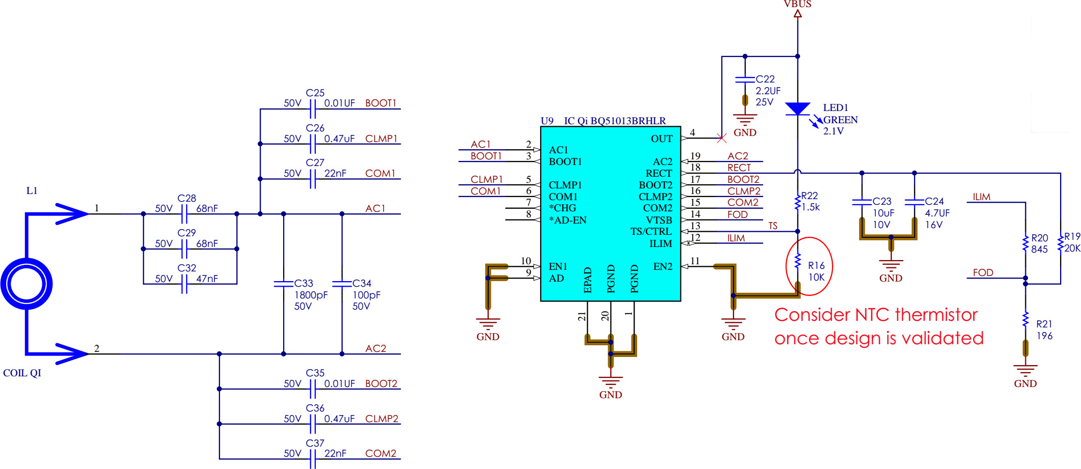

-
Ask a related question
What is a related question?A related question is a question created from another question. When the related question is created, it will be automatically linked to the original question.

