This thread has been locked.
If you have a related question, please click the "Ask a related question" button in the top right corner. The newly created question will be automatically linked to this question.
Tool/software: Code Composer Studio
In DPWM Resonant Mode, How to Limit maximum operating frequency and adjust the DPWM for 50% Duty?
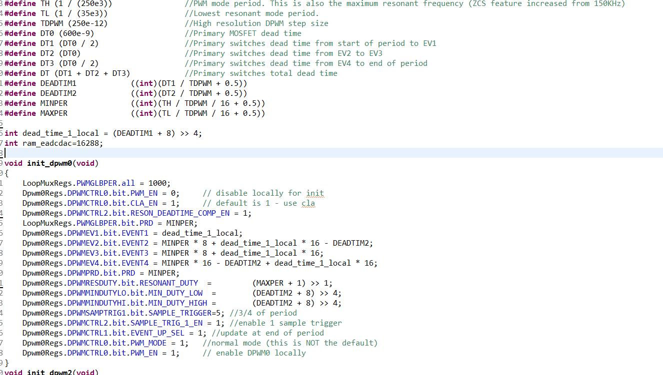
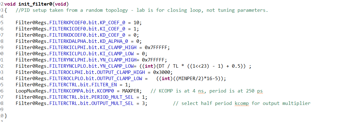
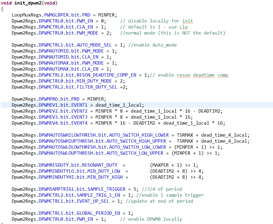
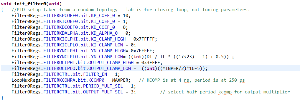
How to Configure the register parameters?I refer to TI LLC HB code,to Configure the DPWM and Filter register。Now I can adjust the frequency by EPA0 input, But i can't Limit maximum operating frequency (Can Limit Minimum frequency ).And I don't konw how to adjust the duty for 50%.
Here are some of my code(If have any suggestion or have any mistaken please tell me):
The maximum frequency is limited by the DPWM auto switch low upper and lower registers. The LLC code is configured so that if the DPWM value goes below that value, it will switch to PWM mode instead of resonant mode. So it will be at 50% duty cycle (minus dead time), until it reaches the value set by the auto switch registers. Then the frequency will stay the same, but the duty cycle will decrease. This is one way to handle very light loads.
The resonant mode is designed to provide 50% duty cycle, minus fixed dead times. I suggest looking in the UCD3138 Technical Reference Manual in the DPWM section 2.6.
Thank you Bob;
I have read UC3138 Resonant Mode & Autoswitch Function.
I add Autoswitch Function. Now i get the 50% Duty Cycle DPWM, But I can't adjust the period by the EAP0 input。
DPWM always stay in the MAX period . I don‘t konw what register i Configured going wrong
Here are some of my code of DPWM and CLA:
I'm not really capable of figuring out which register isn't being set on my own code. I always start with something that works, like the existing LLC code, and slowly evolve it to what I want if it's at all possible. There are over 1500 bit fields in the power peripherals on the UCD. It's easy to spend a week looking for the specific bit. Writing the code from scratch when you have something to work from is a bad idea.
I'm impressed that you can get the LLC going in max period. Normally we can't really get it going in open loop mode because the DPWM starts out at 0, and we never get a trigger. I guess we should try triggering it with another DPWM.
If you do have the whole signal chain actually running, you can try to trace the signals through, just like in an analog circuit and see where the disconnect is
What specific device are you using?
Can you control the filter output using either the high and low clamps or CPU_SAMPLE. If you can change the filter output this way, you can prove that the filter is updating.
Then verify that the filter output is getting to the DPWM. You can read the filter duty register in the DPWM. I think it is also valid for the LLC, and it should be a filter period as well. If that value isn't correct, you probably need to look in the LOOP MUX to make sure that the filter is hooked up to the DPWM correctly
If the filter duty is valid and has the value you expect, then verify that you have all the mode switching stuff hooked up correctly, and make sure that it is enabled.
If the filter duty is changing, but not correct, then you need to look at the signal chain between the filter output and the DPWM.
It's been a couple of weeks since the last access of this, so I'm going to close it.