This thread has been locked.

If you have a related question, please click the "Ask a related question" button in the top right corner. The newly created question will be automatically linked to this question.

LMZ14203H: Circuit based LMZ14203HTZ breaks to shortcircuit after some power ons

Part Number: LMZ14203H

Hello,


We have designed a circuit based on your LMZ14203HTZ/NOPB with 24V input 15 V output. It works but after several units have been assembled, we found that suddenly it breaks, we have 4 LMZ14203HTZ/NOPB that are now a short circuit. Desoldering just this chip and soldering a new one makes de whole circuit work again, so we are pretty sure that this is the only chip being damaged.


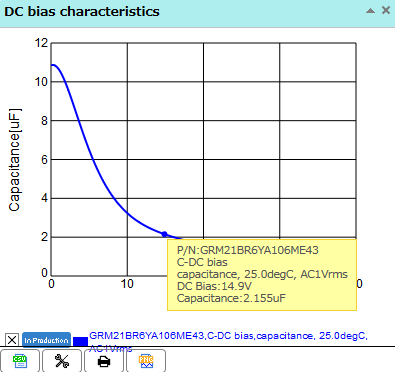
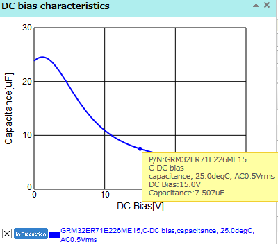
This is the schematic, that is datasheet recommended circuit


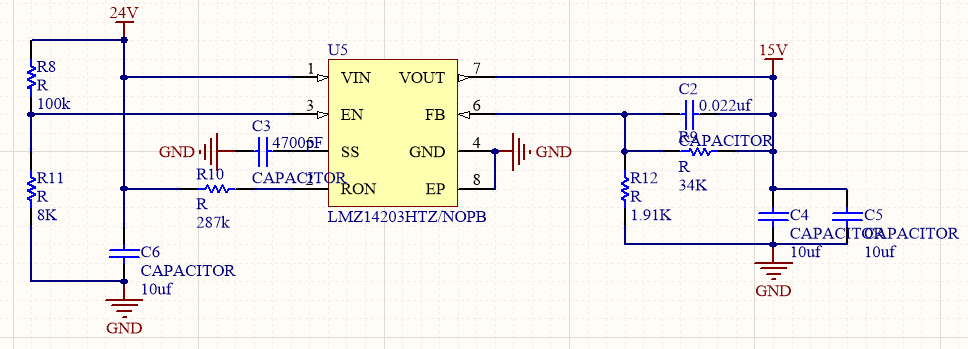
Layout is also copied from datasheet


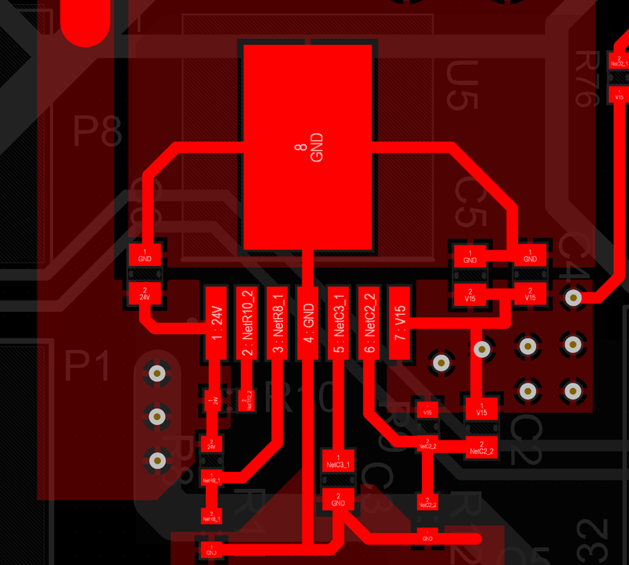
On normal operation it drains 24V@0.18A and supplies 15V@0,28A on power up it could require more current, but in this magnitude.


The conditions for the 3 broken chips were different:


Unit #1 normal operation powered form a dc power supply benchtop. It brokes on power up, so after one power off and power on, it suddenly drains 2A. no change between the power up that makes the circuit broken and several power ups before. It is not clear how to reproduce this


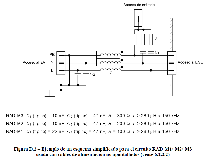
Units #2 and #3. Broken on CE marking lab tests, the power is connected trough a couple/decouple net as the test requires (M2 net model so no PE line that can be seen on this image). With this connection the chip brokes at first power on, on two separate units. it is clear how to reproduce this, but we don’t have this equipment on our facilities

As the circuit is working on certain conditions, and the schematic is copied from the datasheet, the layout is as suggested, could you help us to find the root cause of this problem, and suggest circuit modifications for avoid this problems?


Best regards

  • Hi Raul,

    The schematic you've provided is similar to the typical application in Section 8.2 of the datasheet and PCB follows recommended layout in Figure 50. However I noticed that you might have slightly low effective output capacitance.

    I suspect that this may be a stability issue that caused the short. The output capacitors will experience DC bias effects. Depending on the case size, a 10uF capacitor with 15V DC biasing will have a significantly lowered effective capacitance. Here is an example of a 15DC bias effects on a 10uF / 0805 sized capacitor:

    Notice how a 10uF capacitor at 15V will effectively become 2.1uF. This means your effective Cout is only ~4uF which may be marginally unstable since 10uF minimum is generally required. I'd recommend picking a larger valued / larger package sized capacitor and retest for stability.

    Regards,

    Jimmy

  • Hi Jimmy,

    thanks for your point, didn't know about this effect on ceramic capacitors. looking for some parts with higher nominal capacitance, and bigger package I have found that most of the manufacturers are not placing this kind of information/graph in theris datasheet, and the ones that give this information, most of the times are not reaching 15V, so it is hard to calculate.

    reding some articles, this effect is only related to mlcc and not tantalum. should be a safe decission to go for tantalum lets say 22uf? do you suggest any other capacitor technology/nominal capacitance value?

    best regards and thanks fro your help

  • Hi Raul,

    For reference I use SimSurfing web simulation tool from Murata linked here. You can pick the capacitor value you want and perform DC bias simulations by going through the following path: Characteristics Graph > Individual Characterisitcs Data > C-DC bias > Capacitance/

    I would say tantalum and polymers will experience the same DC bias effects. However MLCC get hit the most with DC bias effects. Tantalum and polymers are more affected by temperature. You should always have one MLCC on the output to have low ESR and better transient performance. It is never recommended to have only tantalum output caps.

    Perhaps you can put 2 of these capacitors on your output for a total of 15uF effective output capacitance. You may want to create a pad for the tantalum cap in case that you want higher output capacitance.

    Regards,

    Jimmy

  • Hello,

    we did a quick test, adding to the 2 mlcc capacitors with effective C = 4 uF a tantalum capacitor in parallel of 22 uF with success. tested on the same conditions none of the 2 tested systems has report any problem

    thank you very much for your support