This thread has been locked.

If you have a related question, please click the "Ask a related question" button in the top right corner. The newly created question will be automatically linked to this question.

TPS2111A: 1V voltage drop when between IN2 and Output

Part Number: TPS2111A

Hi,

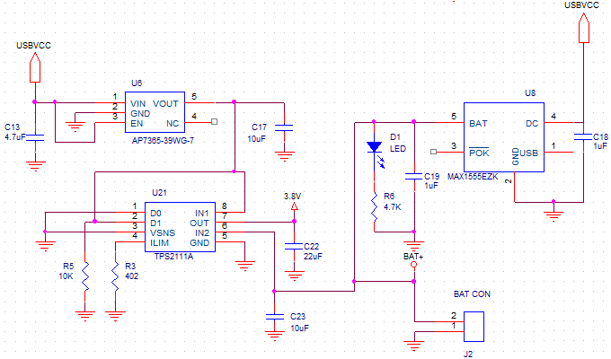
 We are using the TPS2111A to switch power between a Lipo battery and a USB power source(regulated down to 3.8V) to power a device in one of our designs. Recently one of our customers has reported that the device is not wroking properly when the battery is the main power source. We measured the output voltage and there seems to be a 1V voltage drop between IN2 and the output. If the power is supplied through IN1, then it works fine (OUTPUT = IN1). This behvior has appeared around two months of using these devices on two devices so far. We have devices with other customers that have been working for a years now without this failure.   Just wondering what the reason for this behavior could be. We have bypassed the TPS2111A and the device works normally when powered with battery. So there is no issue with the circuit after the TPS2111A. Here's the schematics part that uses the TPS2111A.

Thank you,

  MJ

  • Hi MJ, 

    A few questions regarding the configuration:

    • What are the operating conditions (battery voltage, load current, capacitance).
    • When does the device fail? During startup, during DC? Fails when the battery is plugged in?
    • Any scope shots that you can share of the behavior?
    • You mentioned that two devices failed, how many units is this out of? Is this a prototype or production build?
    • Have you tried replacing the TPS2111A devices on the bad boards? When you do, is the voltage drop fixed?

    Thanks,

    Arthur Huang

  • Hi Arthur,

     Thank you for the feedback.  Here are the answers:

    • What are the operating conditions (battery voltage, load current, capacitance).
      • Battery voltage: 3.6V~4.1V , load current~=500mA rms,  capacitance = 22uF on the output pin
      • The battery the customer is using: 

        https://www.tme.eu/en/details/saft-lsh20/batteries/saft/ls-h20/

        The customer said that he is not plugging USB to the device while the battery is plugged since this is a non-rechargeable battery

    • When does the device fail? During startup, during DC? Fails when the battery is plugged in?
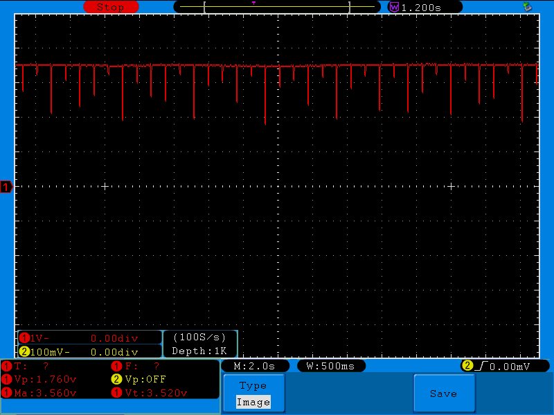
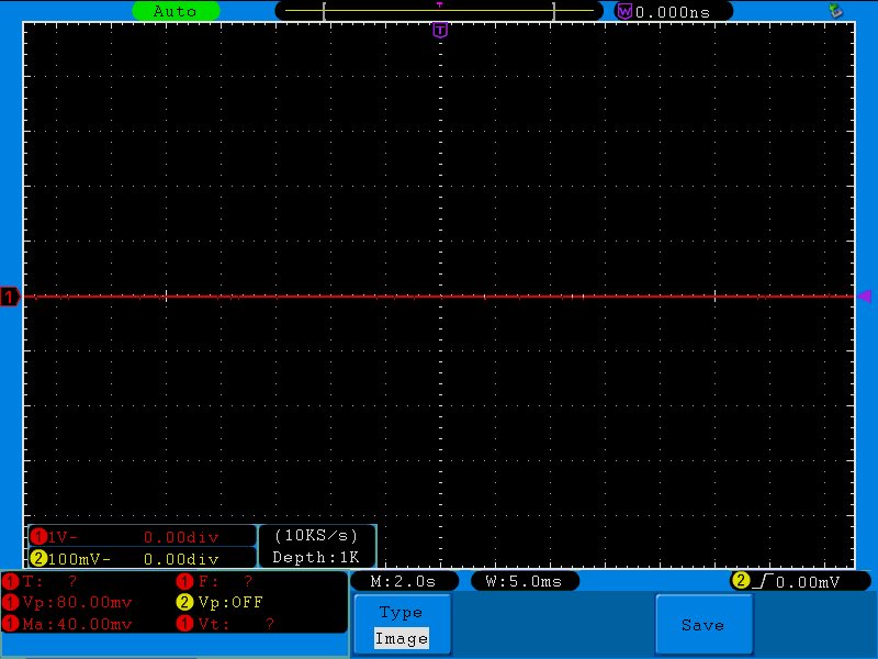
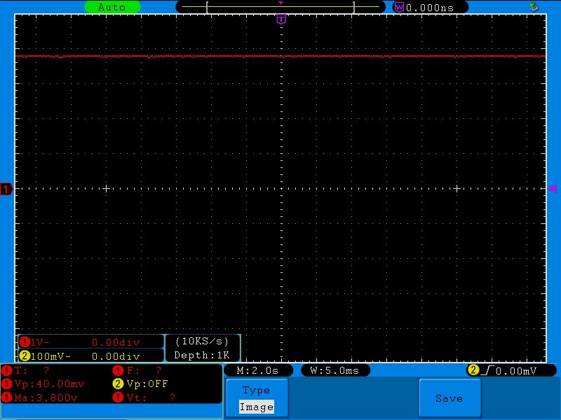
      • Please check scope pictures below This occurs from start up. When power is provided through IN1, the device works normally.
    • Any scope shots that you can share of the behavior?
      • Yes check below.  First one is from a defective device and the second on is from the device we've replaced the TPS2111A on. The test has been done with the same battery on both devices.
    • You mentioned that two devices failed, how many units is this out of? Is this a prototype or production build?
      • This is a production build and this is the first time a customer reports this. The same customer has reported this failure with two devices. All our other customers haven't reported this kind of failure.
    • Have you tried replacing the TPS2111A devices on the bad boards? When you do, is the voltage drop fixed?
      • Replacing it solves the problem.
        MJ
  • Hi MJ, 

    I appreciate the detailed response. At first glance, I don't see anything immediately wrong with the circuit or implementation. The one concern I have is with the battery connection, how is the battery connected or plugged into the system? 

    I would like to see an oscilloscope shot of the initial battery plug in. There could be a voltage overshoot when the battery is plugged in, maybe adding a TVS or a schottky on IN2 would help as well?

    Thanks,

    Arthur

  • Hi Arthur,

    I will arrange an oscilloscope shot by next Thursday as I am out of the office for the next three working days.

      MJ


  • Hi Arthur,

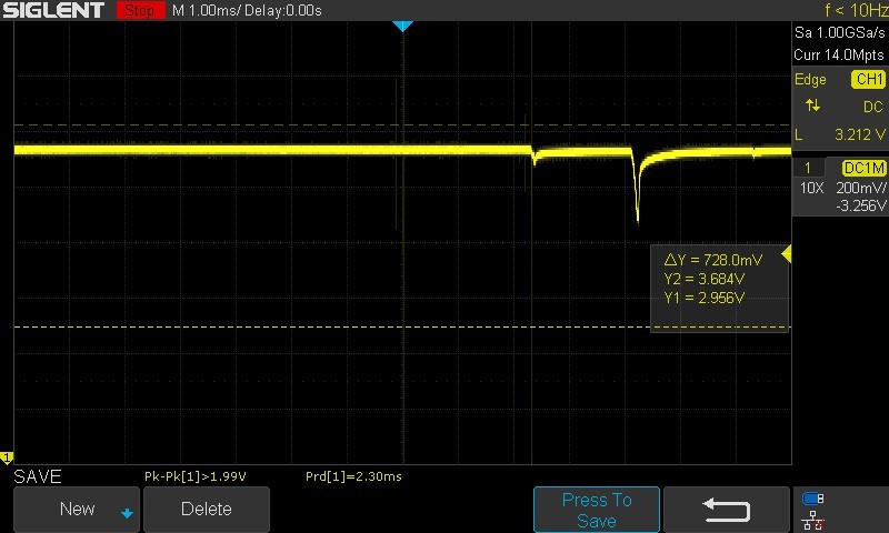
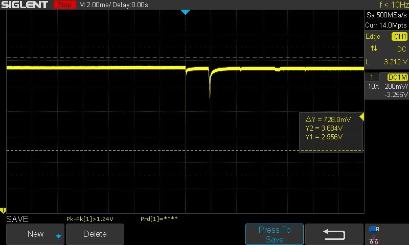
     Here the oscilloscope shots of the initial battery plug in:

  • Hi MJ,

    It doesn't look like your battery voltage is spiking. Here is my recommended actions:

    1. Can you place the "failed" part on an EVM and test if this behavior persists.

    2. Do you have better scope shots of the failure. I would prefer if we can see IN1, IN2, OUT and D1 in this shot. Also can you please make clear the time scale of the dips. 

    3. Could you also take another scope shot of the "dip" zoomed in? I want to be able to see the slew rate of this dips.

    As you can see from the "good" part, this is unexpected behavior. A clearer scope shot will help us understand how the device is failing.

    Thank you for your help and I am sorry for the delay in responses. 

  • Hello Shreyas,

    Thank you for the feedback. I don't have an EVM at hand, so this test is not possible to do currently.

     I will prepare the requested scope shots tomorrow and post them here.

       MJ

  • Hello Shreyas,

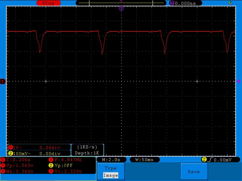
     Here are the scope pictures of IN1 (and D1 since they are connected together), IN2, and OUT. If we leave the device conneted for a while, the ripples disappear but the voltage stays at 3.4V and doesn't rise to 3.8V.

  • Hi MJ,

    The captures were helpful but I think the best course of action is for you to return these parts. 

    https://www.ti.com/support-quality/resources/customer-returns.html

    This would allow us to run testing and further understand the issue. It will also allow us to place the parts on an EVM and confirm if this issue is a faulty part or application specific. 

    Thank you for choosing TI Power Switches in your designs. Once again I would like to apologize for the delays earlier.