This thread has been locked.

If you have a related question, please click the "Ask a related question" button in the top right corner. The newly created question will be automatically linked to this question.

SG2524: SG2524 Current limitation

Part Number: SG2524
Other Parts Discussed in Thread: UC2524

Hello,

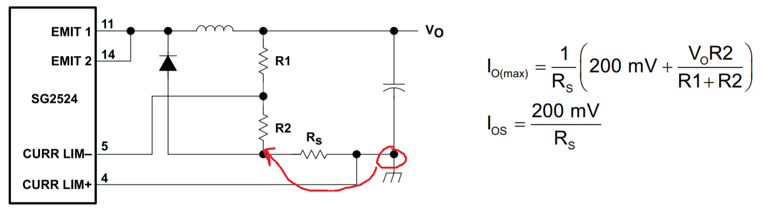
I have a problem regarding the current limitation schematic found on the SG2524 datasheet, i don't understand the expression of Io(max), we can have this expression only if we have the ground between Rs and R2 ( see the figure below).

On the other hand, we are working on a buck converter in DCM mode, is it possible to integrate the SG2524 current limitation in this mode even if the output voltage depends on the load current in the DCM mode?

Thank you 

Kind Regards

N.EN-NASIRY

HW Engineer 

  • Hi,

    This is one of our older devices, please give me a day to see if I can find further information on this topic to help answer your question.

    Thanks

    Peter

  • Hi

    TI does have an equivalent device the UC2524 which has some better reference schematics if you are interested, .

    The formulae from the SG2524 datasheet are using R1 and R2 to set up a current limit setpoint based on the output voltage. The voltage control loop will regulate the voltage across the output terminals in CCM or DCM mode.

    At no load the voltage dropped across the current sense resistor will be 0V, as the load current is increased the voltage dropped across the current sense resistor will increase and start to pull the setpoint, pin 5, set by R1 and R2 closer to ground, the output terminal and the non-inverting pin of the CL amp, pin 4. Once pin 5 drops below pin 4 the CL amp will start to pull the demand signal to the PWM comparator low and pull back the duty cycle.

    Regards

    Peter