This thread has been locked.

If you have a related question, please click the "Ask a related question" button in the top right corner. The newly created question will be automatically linked to this question.

TLV713: Need Drift over time and temp

Part Number: TLV713

Hi Support team

Working on a design in and customer is asking for drift over time and temp and output max variation. 

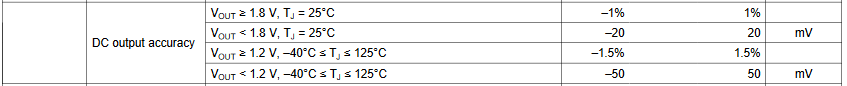
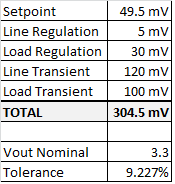
He is looking at a fixed 3.3vout part

Thanks

Jeff C

  • Hi Jeff,

    We do not have this data readily available for the TLV713.  This type of information is not typically gathered for linear regulators.  It sounds like the customer needs a precision reference and not a linear regulator.  One of the first search results in TI's precision references with 3.3V out is the REF34xx component.  It gives a good description of the Long Term Stability testing needed to acquire the drift over time data, for example.  If we were to measure this for the TLV713, we would be at least 1,000 hours away from having this information.  The datasheet also gives drift up to 2,000 hours, which would require at least that much time to gather.

    I would recommend asking if the customer can use a precision reference instead of a linear regulator.

    Thanks,

    - Stephen

  • Hi Stephen

    A reference will not work, I need more current. As for output max tolerance vs typical, I do see a max tolerance listed in our LDO datasheets. I can agree on the long term stability data. 

    Can you come up with a max output range, 

    Thanks

    Jeff Coletti

  • Hi Jeff,

    Let's start by looking at the DC setpoint.  I would use the following snapshot from the table.

    So any fixed output voltage above 1.2V has a maximum of 1.5% tolerance for the DC setpoint.  3.3V * 1.5% = +/- 50mV.
    Next lets look at line and load regulation response. 

    Now lets look at transient responses.  This can be application specific, as it depends on ramp rates, amplitudes and input / output capacitance.
    This plot gives the worst case data because there is no input or output capacitor in the circuit.  The customer will want to assess their transient response given the characteristics of their actual application.

    Line transient = +/- 120mV with no input cap and 25% line step (3V to 4V). 

    Load Transient = +/- 100mV with no output cap
    There are multiple load transient test data sets in the datasheet. 
    I arbitrarily chose this one, but the customer may wish to use one of the others if they more closely match the requirement set.

    Let's add it all up:

    The tolerance will go down significantly if the device has an input and output capacitor.  That will reduce the line and load transient responses.  The responses will further be reduced based on the customers actual line transient amplitude and ramp rate, and load transient amplitude and ramp rate.

    After you have the above calculated, the only item left is the trace loss in the circuit board.  That would be the output current times the trace impedance.  For linear regulators this is typically very low. 

    I am ignoring ripple from the input to the output.  I assume the PSRR is sufficient to squash the ripple on the input and that parameter is negligible in this analysis.

    Thanks,

    - Stephen