Because of the Thanksgiving holiday in the U.S., TI E2E™ design support forum responses may be delayed from November 25 through December 2. Thank you for your patience.

This thread has been locked.

If you have a related question, please click the "Ask a related question" button in the top right corner. The newly created question will be automatically linked to this question.

UC3825: UC3825 Output issues

Part Number: UC3825

Dear colleague,

Our customer encountered a UC3825 issue:

When 2Pin voltage exceed 7Pin(Ramp)+1.25V(Internal), PWM output will change, just output A has output or output B has output.

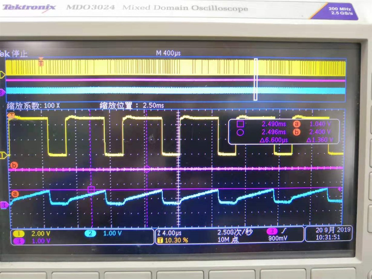
Waveform as below:

Yellow: OUTA output waveform
Blue: sawtooth voltage waveform of 7 Pin(maximum amplitude is 1.04v)
Purple: 2-pin input voltage waveform (2.4v)
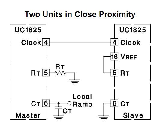
The configuration of 3825 is: external clock input, clock frequency 150K, clock pulse width 1uS.
The internal error amplifier is made into a follower: 1Pin and 3Pin short connection, 2Pin is given an input signal.

Do you need any other materials, please let me know.

Thanks a lot!

Best Regards,

Rock Su

  • Hi Rock,

    Modulation of output pulses is accomplished by comparing the waveform created on the RAMP pin to the output of  error amp. The output stage is disabled during the time when the voltage (RAMP +1.25) is greater than the output of error amp.   A pulse-steering toggle F/F alternately directs the modulated pulse to each of the two output. Thus we can see that  When 2Pin voltage exceed 7Pin(Ramp)+1.25V(Internal), PWM output will change, just output A has output or output B has output.


    Regards,

    Teng