This thread has been locked.

If you have a related question, please click the "Ask a related question" button in the top right corner. The newly created question will be automatically linked to this question.

BQ24773: BQ24773 Standalone Testing

Part Number: BQ24773

Hello TI, 
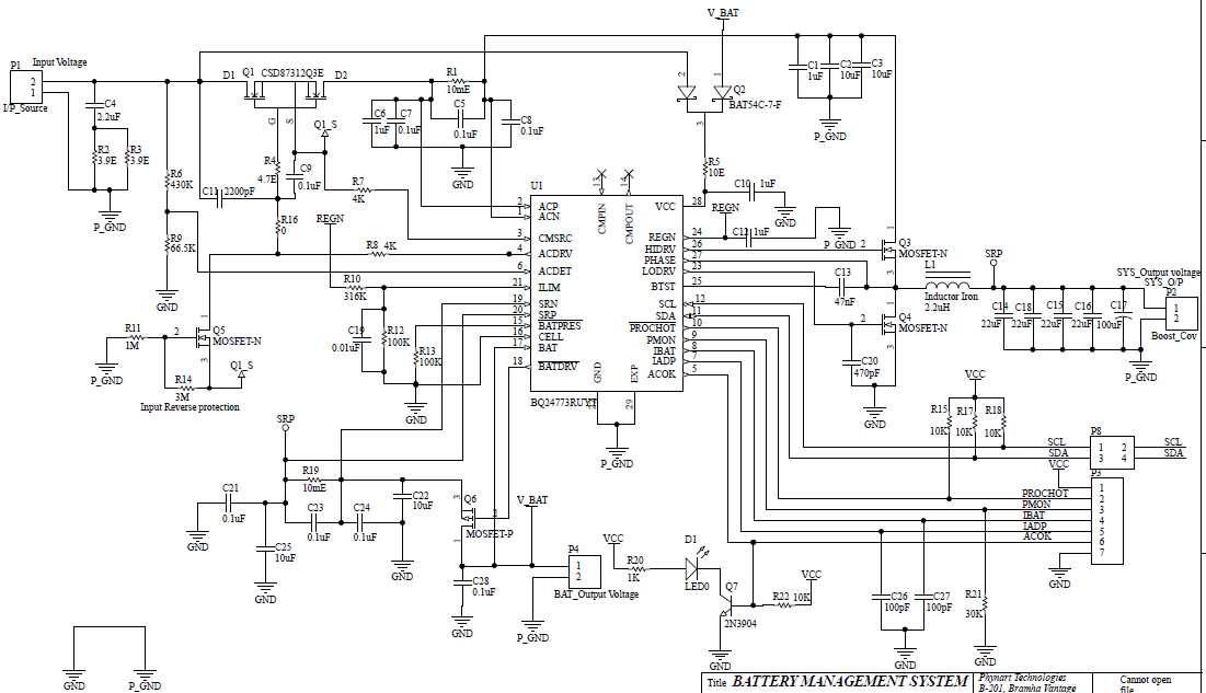
              We prepare BQ24773 Changing module board for testing as per TI EVM recommended reference Schematic 

1. We Design BQ24773 Board able to work without any software configuration ..?
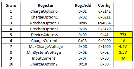
2. Before testing can I Need configure BQ24773 ...?
3. BQ24773 able test with Arduino board ...? if yes please  provide reference code for configuration 

Problem, 
1. we try to test BQ24773 Charging module which is exactly design by using reference of TI EVM Schematic to test basic functionality of IC as per Our system requirements, Its not working ACFET & RBFET not going to trigger 
https://e2e.ti.com/support/power-management/f/196/t/844633


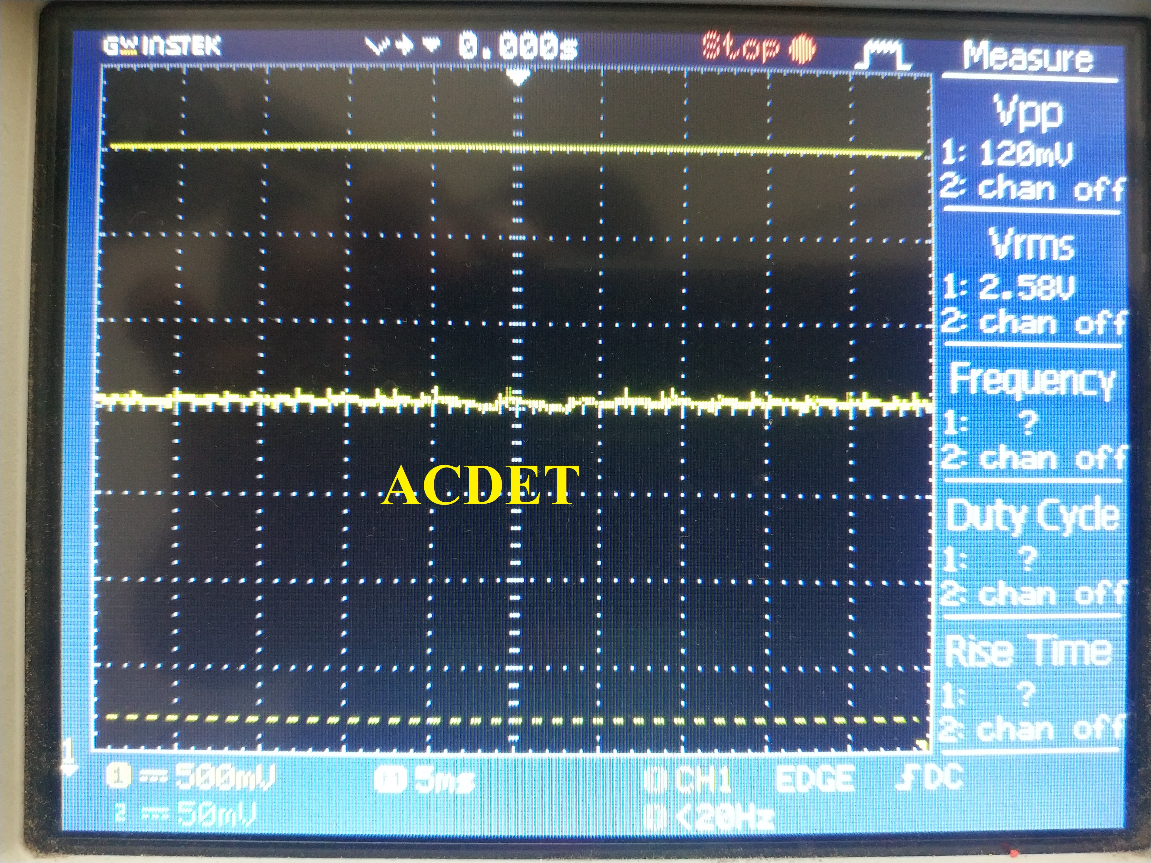
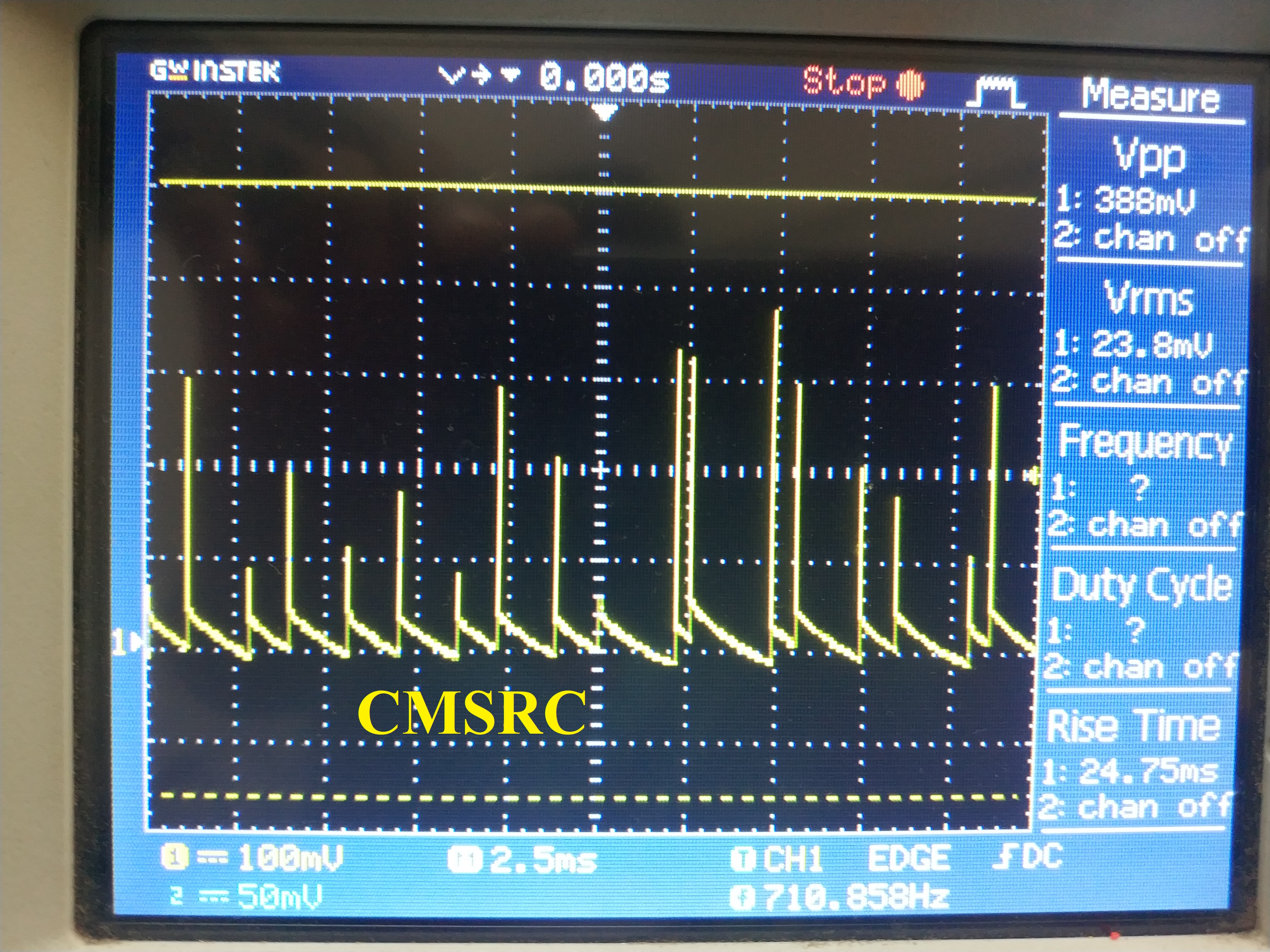
2.by observation ACDRV not changing the state 
   a. Tested on 5V/2.5A & 12V/1A adapter also tested on more than 12v by using linear power supply 
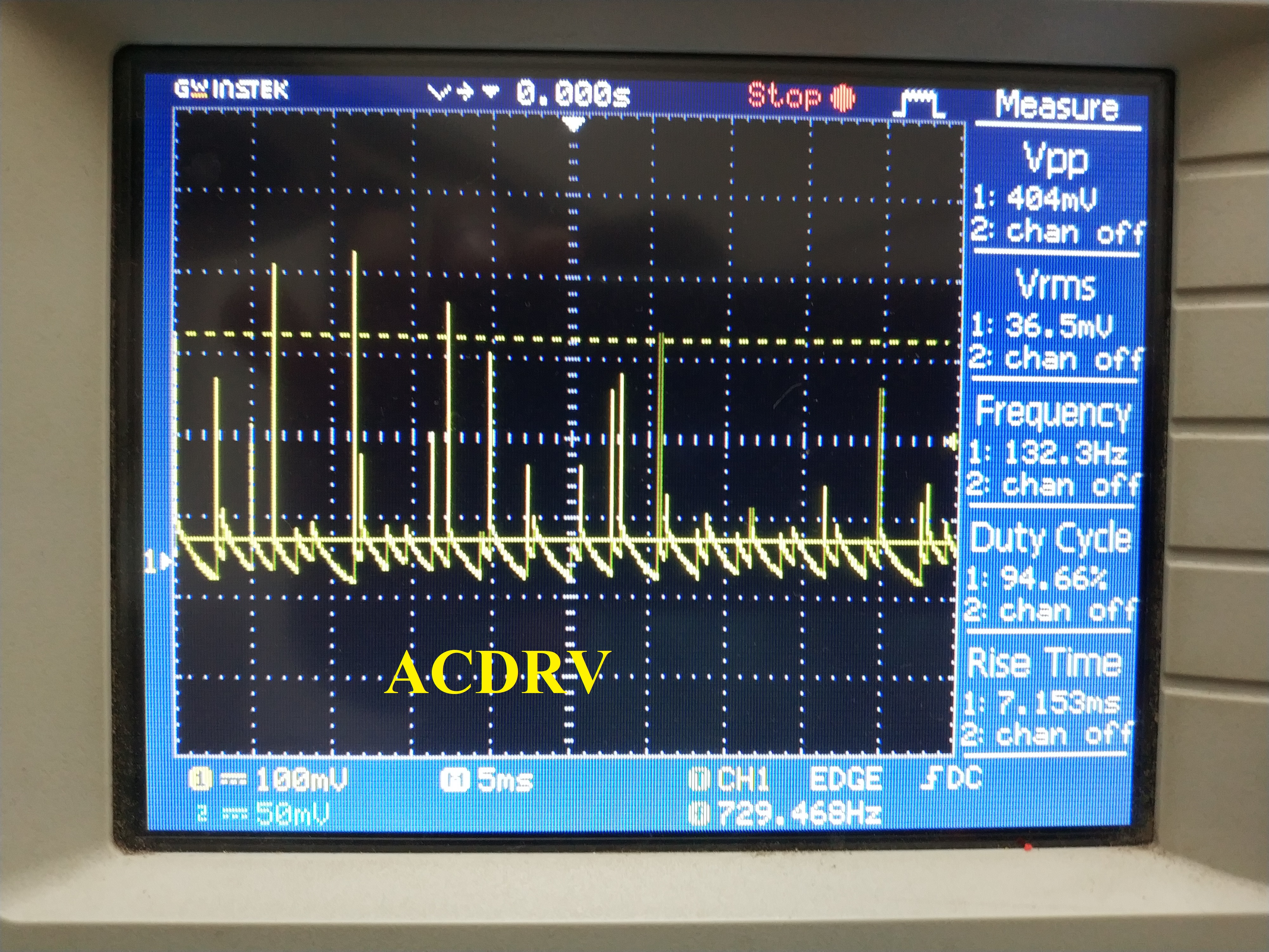
   b. Tested on ACDET > 2.4V
   c. Observe some drop between I/N voltage(5V) and VCC(4.5V)
   d. when Input is applied REGN is 0.7V
   e. ACOK not going to change state always in some mV 
All above condition tested with Battery(Lithium Ion 2200mAh-3.7V) & Load(2W) and without battery & Load
https://e2e.ti.com/support/power-management/f/196/t/844044

BQ24773 require any software support or its able work without any Software support standalone ..?


If require any software support configuration test basic functionality of BQ24773 please provide related document and reference code, thanks for your valuable support and response   

For the reference BQ24773 charging IC Schematic 
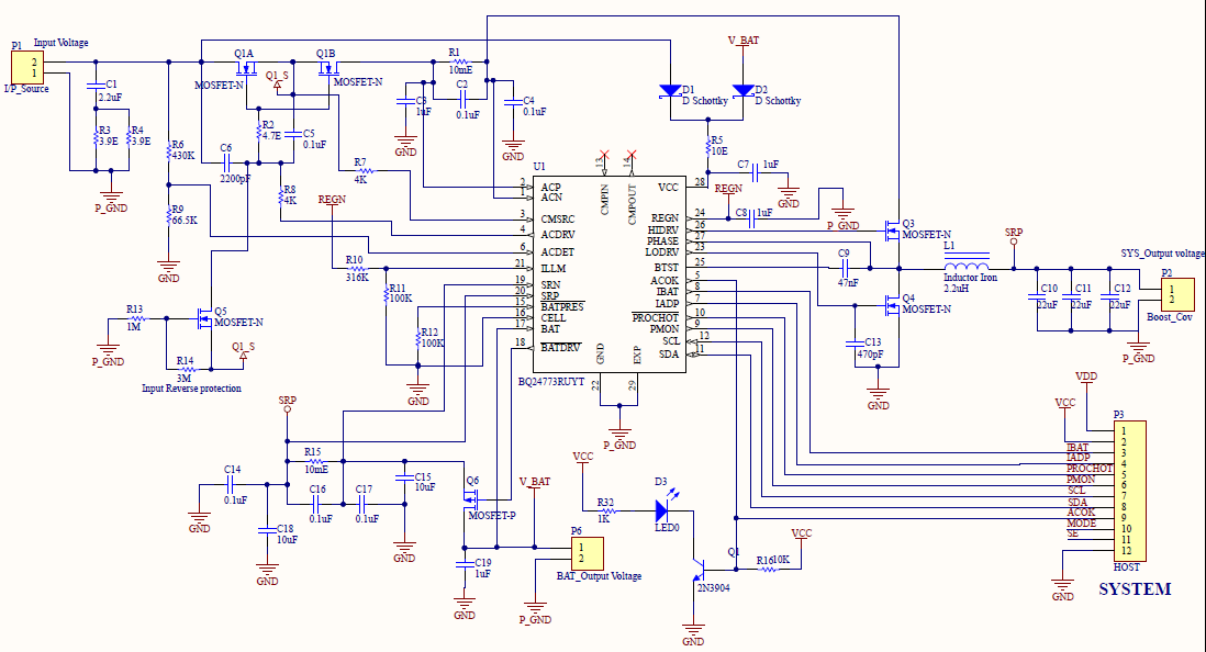
Thanks and Regards,
Rahul Surawase 

  • Hey Rahul,

    1. The BQ24773 charging portion will not function without programming the device.

    2. Yes, you need to configure the BQ24773 in order to charger. However, the system rail will be regulated as long as a valid input source is present.

    3. We do not have reference to work with any particular controller or host. There is a third-party firmware written for the charger here: https://chromium.googlesource.com/chromiumos/platform/ec/+/master/driver/charger. However, please note this code is third-party and not supported or created by TI, so perform your own due diligence when coding the firmware.

    For sake of consistency Rahul, I will loop in the other threads you have posted here, as the issue is getting a little confused between your various posts. I will close the other threads and respond to this thread.

    https://e2e.ti.com/support/power-management/f/196/t/844044

    https://e2e.ti.com/support/power-management/f/196/t/844633

    1. Please refer to my comment no.8 in the previous threads:

    8. I think we need to look at a startup waveform showing the ACDRV voltage and CMSRC voltage, the VCC voltage, and the SRN voltage. You should overlap the ACDRV voltage and the CMSRC voltage ground point. I would also capture the ACDET voltage with 500mV/div at least to capture the change in the input.

    This waveform will help us get closer to determining why the ACFETs are not turning on and why the ACOK status is still low.

    Regards,

    Joel H 

  • Hello Joel,

                     I try to write code on Arduino for BQ24773 Configuration, but we facing some issues 

    1. Fail to read written data on register, reading register written data by using logic analyzer  

    2. Can you please send right sequence of register and value of registers for configuration

    3.MaxCharge voltage , ChargeCurrent and InputCurrent not going to set as per the requirement, there is any dependent register of this registers ..?  

    4. Setting of other register affected on this register..?

    5. what is the right register configuration of 5V/2.5A register to get VSYS= 5V/1A on charge current 1A ..?

    Thanks and regards, 
    Rahul Surawase 

  • Hello Joel, 


                     We configure the system by using Arduino and cross verify register data by reading the registers 

    Check configuration setting  
          We have same issue which observe before, no change in system voltage REGN shows 0.7volts and ACDRV voltage not going to change still 0v or  <100mV

      There is anything wrong ..? we can't figure out where is the issue, Please verify above mention schematic and configuration setting 

    Thanks and Regard,
    Rahul Surawase

  • Hey Rahul,

    Again, I am still looking for a waveform as mentioned previously.

    Can you please provide this to move forward?

    Regards,

    Joel H

  • Hello Joel,
                      TAke look ACDR waveform which observe on config setting as per mention in config image, there is no any change in REGEN and ACFET & RBFET 

    1.Input adapter= 5.2V/2.5A

    2.Battery(Lithium Ion) = 2200mA (3.7 O/P)

    After configuration by using Config1 setting,

    1.Vsys= 3.84V
    2.ACDET=2.6V
    3.ACOK=10mV
    4.PROCHOT=3.2V
    5.HIDRV= 3.5V
    6.LODRV=0.7V
    7.REGN=0.7V
    8.VCC=4.8V 
    9.ACDRV=400mV
                                  Observe voltage ..!


    Thanks and regards, 
    RAhul Surawase

  • Hello Joel,

                          As per your requirements we capture startup waveform, 

    8. I think we need to look at a startup waveform showing the ACDRV voltage and CMSRC voltage, the VCC voltage, and the SRN voltage. You should overlap the ACDRV voltage and the CMSRC voltage ground point. I would also capture the ACDET voltage with 500mV/div at least to capture the change in the input.

    This waveform will help us get closer to determining why the ACFETs are not turning on and why the ACOK status is still low.

                      Sorry for the delay...!

    Thanks and Regards, 
    RAhul Surawase 

  • Hey Rahul,

    Let me review these waveforms and get back to you.

    From what I can see, the ACDRV-CMSRC charge pump is attempting to turn on the MOSFETs, but it appears some other event is triggering it to shut the MOSFETs off again. It is possible that the input MOSFET gate charge is high, leading to a slower turn-on time.

    I also re-reviewed your schematic, and it looks like you don't have any input capacitance on the input rail to the buck converter. This is between the HSFET and the RAC resistor. Our EVM has 2x10uF capacitors on that rail, that you are missing. I am not certain if this is the culprit yet, but I have another suspicion that the inrush current from the moment the MOSFETs turn on (which is brief) is large. Granted, more capacitance would increase this inrush current, unless it helps slow the RBFET turn on time. I would try adding these 20uF to your board, similar to the EVM's C2 and C3 capacitors. 

    And to confirm, ACDET here is always above 2.4V, correct?

    Is there a load on the system side when the adapter plugs in?

    You also mentioned you tried with a 12V power supply, and same result, correct?


    Regards,

    Joel H

  • Hello Joel, 
                      What about the ACOK and REGN LDO ..?

    What is the ACOK status when Input adapter is connected, It's need to be High right ..? but its not going change the state its always Low shows 10mV

    REGN LDO also shows 0.7V only, expected REGN voltage is 4.4 right ..? what is reason of that behavior ..?

    Also satisfy all this below mention conditions 

    • V(UVLO) < V(VCC) < V(ACOVP)

    • V(ACDET) > 2.4 V

    • V(VCC) – V(SRN) > V(VCC_SRN_RISE)


    And to confirm, 1. ACDET here is always above 2.4V, correct?

    ACDET set to 2.56V by Using R6 100K & R9 100K when Vin is 5.2V

    2. Is there a load on the system side when the adapter plugs in?

    No, there is no any load on the system side but we also check with load by using 1W DC load  there is no any change found on System performance 

    3. You also mentioned you tried with a 12V power supply, and same result, correct?

    YES, not found any difference with 12 V adapter 

    Also check with C2 10uF and C3 10uF capacitor inserted between HSFET and RAC resistor no change Input waveform of ACDRV and CMSRC signal 

                                   waiting for your valuable response   ...

    Thanks and Regards,
    Rahul Surawase

  • Hey Rahul,

    A few comments:

    ACOK is based on the ACDET voltage, the VCC voltage being above the UVLO threshold, and VCC being above the battery voltage. 

    What is not clear to me looking at your ACDRV-CMSRC voltage is the spike in the CMSRC voltage. 

    Let's try a couple of other things:

    1) Short across the R1 resistor and retry your test. I am trying to see if this is a product of an inrush current spike that is hitting some over-current condition and disabling the input FETs. If you short across RAC, the differential voltage will be small for any amount of current.

    2) Just to confirm everything is connected correctly, short across Q1 (from D1 to D2), and remove R7 and R8, and tie the ACDRV and CMSRC pins together with a 500-kOhm resistor. This should confirm whether the rest of the charger is operating correctly.

    Regards,

    Joel H

  • Hey Rahul,

    Were you able to run the tests above?

    Regards,

    Joel H