This thread has been locked.

If you have a related question, please click the "Ask a related question" button in the top right corner. The newly created question will be automatically linked to this question.

TPS61022: No over-current protection?

Part Number: TPS61022

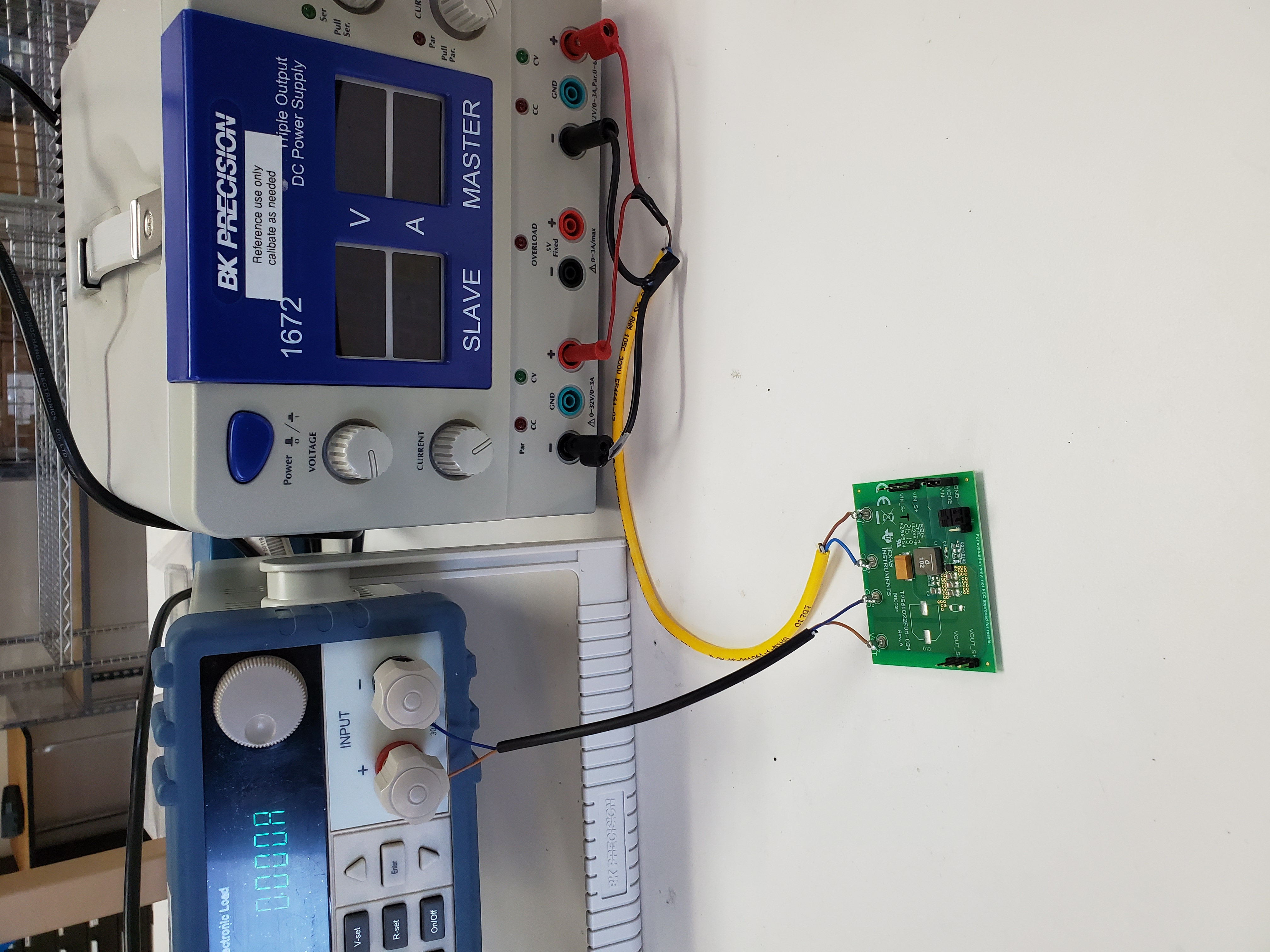
We had several TPS61022 failures in our prototype boards and in order to isolate the problem, conducted a simple lab experiment with two eval boards TPS61022EVM-034. Modification included setting the output voltage to 5.45V by replacing R3 with 61K (this created a feedback voltage divider 750k+61k)||100K). For testing we used a regulated 3V lab power supply on the input and a BK Precision 8500 programmable DC electronic load on the output. Board #1 was set to PFM mode. The current was slowly increased from 0 to 1.4A. At 1.4A the board was running but after setting the current to 1.45A the board ran for 6 min and then died shorting the lab power supply.Board #2 was tested in PWM mode. The board ran ok at 1.4A but failed immediately at 1.47-1.48A. Both damaged boards show the shorted inputs. 

Last more or less stable operation in PWM mode:

Vin = 3V, Input current = 3.6A

Vout = 5.32V, Output current = 1.4A

Whats wrong with this part? I cannot remember last time a TI switcher failing so miserably


  • Hi Andrew,

    I will do a bench test soon and let you know the result.

  • Hi Andrew,

    I did the same test on EVM under condition of Vin=3.04V, Iin=2.79A, Vout=5.448V, Iout=1.5A. The test last for 2 hours and found no failures.

    When you did this test, have you changed other components, like Cout, inductor L? You test result looks unreasonable because the efficiency is much lower than standard EVM. 

    How did you measure the current and voltage? What' the power supply current limit setting? 

  • The power supply is rated for 5A. The input voltage/current reading were taken from the lab power supply meters, while the output voltage was monitored by the programmable dc load. I made no other changes to the eval board except replacing R3. Try to slowly increase the load current and let me know where it shuts down and if it ever comes back

  • Hi Andrew,

    The long input cable has big voltage drop if input current is high. Don't read the power supply meters because it's not correct. Use DMM to measure Vin on EVM Vin sense pins. I guess the real input voltage of your EVM now is around 2V, not 3V.

    Can you use digital oscilloscope to probe SW pin, Vout pin waveform to see if there is any instability?

  • Hi Andrew,

    I use the EVM to do the test again. Vout is set to 5.45V same with yours. Input power supply is set to 3.0V and current limit point is 7A. I increase the load current from 0A to 2.7A slowly and decrease it to 0. And let the board keep working at 2.7A load current for 10 minutes, No failures found.

    Can you show me the hardware picture of the EVM and bench setup? Can you replicate the failure again on another EVM?

  • I've searched through this forums and noticed several other messages about TPS61022 getting suddenly and inexplicably damaged. None of these inquires have been resolved and in all these cases you have not been able to replicate the problem or explain what could've caused it. At this point I have zero faith in this part and sadly, very little hope that TI is capable of helping us to troubleshoot the problem. Before checking out, I'd like to ask you few simple questions.

    1) Can you list three most probable reasons for the sudden death of TPS61022 eval board?

    2) Can it be overload?

    3) How much current can the internal FET switch support?

    4) At Vout = 5.5V, can it be the ringing on the output causing OVP?

    5) Can it be instability caused by input wire inductance or some abrupt drop of the input voltage? 

    6) Can it be the fact that we are using a programmable DC load, which maintains the output current for much longer while the IC is trying to shut down? 

  • Hi Andrew,

    I understand your disappointed feeling for the failure. Actually millions of units have been used on customer's board and only very few customers told us they units failed on E2E, VERY LOW failure rate. I'm willing to help you resolve the case so every time I saw the failure post, I went to lab and tried to replicate the problem as soon as possible. It's very important that you told us the detailed hardware setups. The main reason is normally TPS61022 efficiency could not that LOW from your description, only 5.32v*1.4A/(3V*3.6A)= 68.96%. That's why I said "Can you show me the hardware picture of the EVM and bench setup? ".

    Below is my answer:

    1) We never saw sudden death of eval board if we follow the EVM user's guide. Make sure input cables thick enough and not too long.

    2) Yes. TPS61022 has output short-circuit protection, thermal shutdown protections and 8-A switch current limit functions,

    3) TPS61022 datasheet said clearly it has 8-A (typical) switch current limit.

    4) We don't suggest setting Vout=5.5V. Because OVP minimum spec is 5.5V. Considering the output voltage ripple and load transient overshoot, it's highly likely that it will trigger OVP thershold.

    5) Yes. That's why I ask you share the bench hardware photos. Long, thing input cables has very high parasitic inductance. If the eva board is working at high output current conditions, hence input current will also very high. If shutting down the device immediately, this high parasitic inductor may cause high input voltage overshoot. TPS61022 VIN pin absolute maximum voltage rating is 7V, so this overshoot may kill the device.

    6) A programmable DC load won't kill the device because if IC could not handle that high current, the eval board Vout will decrease till to 0V. DC load then will no longer absorb current from IC. If you are using a source meter, it may kill the IC. Source meter is a current source, keep absorbing current from IC even Vout is 0V. So Vout may go down below 0V and be negative, which is lower than datasheet requirement -0.3V. We used to see source meter kills IC in lab.

  • Hi Zack

    Here is photo of a lab setup. On the left is a programmable dc load BK Precision 8500, on the right is a power supply with two paralleled outputs. The picture is intended to show the length of cables (we used a different lab ps for testing). If I understand your #6, if a converter TPS61022 is connected to a constant current sink, this can kill a converter during an OVP shutdown.  When you wrote earlier that you could not reproduce the failure, had you used a programmable dc load or a variable power resistor? We tested a converter by setting a  programmable dc load as a constant current sink.  

  • Hi Andrew,

    I'm using a Chroma 63103A DC Electronic load. This E-load won't sink current if voltage is below 0V. So I didn't see the failure. But I did see the source meter will kill the device.

    In the picture you share, the input & output cables are too thin, parasitic inductor and resistor cause input voltage drop. If you measure J7 Vin_S+, Vin_S-, it will shows the real input voltage on board. Can you use digital oscilloscope and measure VIn, SW, Vout pins waveforms to see if there is any instability?

    Do you have another good evm or prototype board? Set the Vout = 5V, use a short, wide input & output cable and do the test again in Vin=3.0V, Vout=5.0V, Iout=1.5A condition.

  • Hi Andrew,

    Do you have the same problem on prototype boards? If so, maybe you can send one prototype board so that I can test in TI lab.