This thread has been locked.

If you have a related question, please click the "Ask a related question" button in the top right corner. The newly created question will be automatically linked to this question.

LM2742: connect to two UCC21710-Q1 to drive MOSFETs

Part Number: LM2742
Other Parts Discussed in Thread: UCC21710

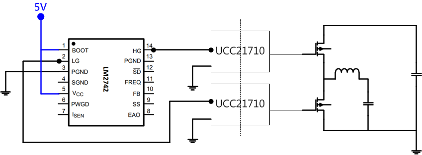
Hi, I'm designing a buck converter, which a LM2742 is used to drive the low voltage side of 2 UCC21710s, as picture below shows.

  1. I want to make sure there won't be any ground level issue by "connecting BOOT with Vcc" & "HG / LG to 2 driver ICs with same ground level", since LM2742 is originally designed to directly driving a half-bridge of power converter.
  2. Also, without directly driving a half-bridge, I'm confused with the necessity of PGND/SGND separation.
    1. Do I need to "cover HG/LG with PGND plane(Digital signal)" and "cover FB/EAO with SGND plane(analog signal)"?
    2. Or there won't be any differences when LM2742 is not directly driving a half-bridge?

Thanks for your advise!

  • Chih Kuo Hu,

    Since your use case is outside the typically application for the LM2742, I

    need research the design and respond later. 

    Is it necessary to isolate the controller from the power stage?

    What are the voltage and current levels of the buck converter?

    How are you planning on closing the feedback loop?

  • Hi David,

    Thanks for your reply. Your questions have been answered as follow.

    Is it necessary to isolate the controller from the power stage?

    =>Actually, the power stage isn't isolated from the controller, the 2 ground sign are the same(sorry for the dash line of lower UCC21710 which might cause your misunderstanding).

    What are the voltage and current levels of the buck converter?

    =>The voltage is around 300V-750V and the current is around 20A-60A (a 18kW circuit).

    How are you planning on closing the feedback loop?

    =>I will use a differential amplifier to measure the output voltage of the converter and filtered it before it flows into LM2742's FB pin.


    Best Regards,

    Chih Kuo

  •  

    Since the LM2742 is an older design and your application is outside

    the use case of driving an half bridge, I have been unable to

    find the resources needed to answer the questions and some of the concerns.

    The VCC is only 5V for the LM2742 and your design is >300V and 18kW, I think having a quiet (analog signal)

    ground is recommended for the feedback control loop.

    Have you considered an UCC controller for your application?

    I do not see an issue with coupling the VCC to BOOT and keeping the quiet and switching grounds separated.

    Consider using a RC to filter voltage going to the VCC pin.

    However, the device has circuits for current limit by sensing the voltage across the low side fet and

    to prevent overlap of the high and low side drivers and I am not sure of the behavior in your application.

    I would recommend evaluating the device with your configuration.